Presented here is an example of how you might go about implementing a traditional 2D isometric map using SFML. I chuckle as I write this, since SFML is just a 2D front-end sitting on top of OpenGL which is, of course, a 3D API. Nevertheless, SFML is implemented to be a 2D library, and so it might be nice to have an isometric map system that works with SFML without having to delve into OpenGL.
At the end of this article, we will have a working 2D isometric map of arbitrary size, with a basic tile-based lighting scheme, suitable for some sort of graphical roguelike or other 2D RPG-type game. I will provide all of the code, and a working demo. I will discuss the structure of the map, the organization of the lighting scheme, how it all fits together with SFML. I will also touch on a few of the issues and caveats that crop up when using an old-school 2D system, and why using 3D makes things so much easier.
To see what we are shooting for, here are a couple screenshots of the final product:
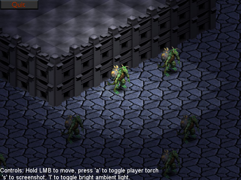
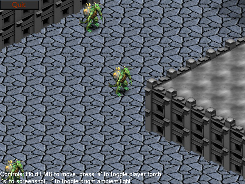
Now, I explain in the remainder of this post how the system works. If you don't care, already know enough about isometric maps, etc... and just want to get to the code, here is the archive:
Included is all the source, including source to bind SFML to Lua, the isometric map code presented here, and a small sample Lua application demonstrating the system. Tinker to your heart's content. Be warned, though, that this has been sitting on my harddrive mostly untouched for a couple years now, and there might be bugs a-lurking. Since it's not code I commonly use, it hasn't been very thoroughly tested.
[page]
The Map, Basics
First of all, this isn't really isometric. See (Axonometric Projections) for an explanation of the various types of projections that are collectively referred to as "isometric" when talking about games. The scheme I prefer is the dimetric projection with an azimuth angle of 30 degrees.
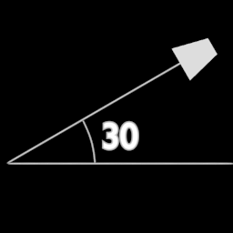
This results in tiles that are twice as wide as they are tall on screen, and is the "typical" axonometric projection used in games such as Diablo and Diablo 2. The 2:1 tile ratio size makes creating artwork for the game a bit more convenient, and the math for dealing with this type of projection is very simple. The camera is also rotated around the Up Axis by 45 degrees. When viewed from this angle, here is what a cube looks like:
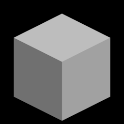
You can see how the top of the cube forms a diamond. This diamond is exactly twice as wide as it is tall. This is our 2:1 projection. Of course, when using pure 2D techniques, we don't worry about rotating the camera at all. 2D "fakes" this perspective using specially-crafted graphics and a layering system. You merely are drawing 2D images directly on-screen in a fashion that mimics a 3D view.
With questions of view angle out of the way, we can get down to the map. The map is going to be a simple 2D array of cells, where each cell is a box. The box can have a floor, a roof, and 2 walls along the front edges of the cell. It can also contain some set of objects, possibly dynamic. The cube in the previous image is a good representation of this. The top diamond is the roof, the floor (which is blocked by the walls) is also a diamond, and the left and right walls can be seen connecting the roof to the floor. The map will be a whole array of these boxes. Some boxes won't have any walls or roofs, and will be floor only, plus any objects. Others may have only walls, with no need of a roof. Still others may be roof only. Boxes also act as containers for objects that can move around.
When a map is created, the size of the boxes must be specified, especially the X and Y sizes (width and length), as these determine the size of the world space. Since we are using cells that are equally sized along X and Y, we will denote the cell dimensions as NodeSize. One node is NodeSize units wide, NodeSize units deep, and an arbitrary number of units tall. (Height of a box does play a part in rendering, but less of an important part than width and depth).
Now, since this system is based on SFML, it makes sense to make each of our various drawable types (walls, floor, roof, objects) to be of type sf::Sprite. A Sprite associates an image to draw with a set of data describing where to draw it, how large to draw it, etc... However, the position, orientation, and so forth, of the sprite is interpreted as the on-screen position/orientation in which to draw the sprite. A Sprite doesn't have any knowledge of world coordinates, just screen coordinates.
In this kind of isometric view, world coordinates are different than screen coordinates. Screen coordinates are used only for drawing on the screen, and they represent a modified form of the world coordinates; a projection of the world coordinates onto the screen, so to speak. World coordinates represent a given object's location in the world, and operate within the grid of boxes that comprise the map. These coordinates are actually 3-dimensional, since an object can be located above the ground. So each object in the world actually has 2 sets of coordinates that must be tracked, and since a Sprite can only have a single position (the screen coordinates) we need to extend sf::Sprite to incorporate a world position. This is pretty simple:
[spoiler]
class IsometricMapSprite : public sf::Sprite
{
    public:
    IsometricMapSprite();
    IsometricMapSprite(const sf::Image ℑ, const sf::Vector2f &position=sf::Vector2f(0,0),
        const sf::Vector2f &scale=sf::Vector2f(1,1), float rotation=0.f, const sf::Color &color=sf::Color(255,255,255,255));
    ~IsometricMapSprite();

    void SetWorldPosition(float x, float y);
    void SetWorldPosition(const sf::Vector2f &position);
    sf::Vector2f GetWorldPosition() const;

    void SetWorldZ(float z);
    float GetWorldZ(){return m_z;}

    void setUseLighting(bool use){m_uselighting=use;}
    bool getUseLighting(){return m_uselighting;}

    protected:
    sf::Vector2f m_worldpos;
    float m_z;
    bool m_uselighting;
};
[/spoiler]
The IsometricMapSprite directly inherits from sf::Sprite, and adds a few members and methods for maintaining a world position and Z-height above the ground. (There is also a member, m_uselighting, which I will get to in a bit, in the section on lighting). The interesting parts of the class are SetWorldPosition and SetWorldZ. These methods will set the world coordinates of the object, and will calculate the on-screen coordinates for the sprite for later rendering.
Converting From Screen to World and World to Screen
Since we have two different coordinate spaces, we need to be able to convert a point from one to the other. Screen space is the 2D rectangular view-space of the screen. When a window's default View is set, Screen(0,0) is located at the upper left hand corner of the screen, Screen(W,H) is located at the lower right corner and is dependent, of course, on the size of the viewport. The view is actually just a rather small window into screen space, which is theoretically infinite; using the sf::View:SetCenter method, you can move the view rectangle around to view different parts of screen space. The World Space is different. World(0,0) is located in the very upper-left corner of of the world cell whose map index is [0][0], World(NodeSize,NodeSize) is located in the world cell whose map index is [1][1], and so forth. The World space is the space in which gameplay mechanics, object movement and interaction, and so forth take place. World Space is bounded by the dimensions of the map in cells (the size of the map array) multipled by the NodeSize parameter. So a map with (128,128) cells and a NodeSize of 32 has a World Space of (4096,4096). All objects in the world must have coordinates within the range (0,0)-(4096,4096) or they will lie beyond the edges of the map.
The equations to convert between World and Screen spaces are actually fairly simple:
// Function to convert a world position to a screen (view) position
// ScreenX = 2*WorldX - 2*WorldY
// ScreenY = WorldX + WorldY
sf::Vector2f WorldToScreen(sf::Vector2f v)
{
    return sf::Vector2f(2.0f*v.x - 2.0f*v.y, v.x + v.y);
}

// Function to convert a screen (view) position to a world position
// WorldX = (ScreenX + 2*ScreenY)/4
// WorldY = (2*ScreenY - ScreenX)/4
sf::Vector2f ScreenToWorld(sf::Vector2f v)
{
    return sf::Vector2f((v.x+2.0f*v.y)/4.0f, (2.0f*v.y-v.x)/4.0f);
}
By these equations, we can easily convert a world coordinate to a screen coordinate. We can use WorldToScreen to automatically set a Sprite's screen coordinates whenever the object's world position is modified via SetWorldPosition and SetWorldZ:
[spoiler]
void IsometricMapSprite::SetWorldPosition(const sf::Vector2f &position)
{
    m_worldpos=position;
    sf::Vector2f screenpos=WorldToScreen(m_worldpos);
    screenpos.y -= m_z;
    SetPosition(screenpos);
}

void IsometricMapSprite::SetWorldZ(float z)
{
    m_z=z;
    sf::Vector2f screenpos=WorldToScreen(m_worldpos);
    screenpos.y -= m_z;
    SetPosition(screenpos);
}
[/spoiler]
Note the special handling for an object's World Z coordinate. Moving up on the conceptual Z axis in World space translates directly to moving up on the Y axis in screen space. Here, I am moving up Screen Y on a 1:1 basis with World Z, simply by subtracting World Z from Screen Y. This is a bit disingenuous, since in a true 3D projection, the Up axis in world space is foreshortened a bit (in point of fact, an object 1 unit tall in world space would be cos(30) or ~0.866 units tall in Screen Space, given our 30 degree azimuth angle.). However, since we are faking it, we can make 1 Z unit in World Space == 1 Y unit in Screen Space. This simplifies the math a bit. If it bugs you, just multiply m_z by 0.866 before subtracting from Screen Y.
Now, when we call a Sprite's SetWorldPosition() method, the screen coordinates of the Sprite are automatically calculated. Thus, we never call SetPosition() on a Sprite directly; only SetWorldPosition. This way, we can perform AI and movement, logic, etc... on world position, and let the system itself worry about where on screen to draw it.
[page]
Implementing the Map
In order to implement a map, we need to clarify what exactly a map cell or box is. The map itself is very simple, just a 2D allocated array of map cells. Outside of rendering the map, the map cells do most of the work of storing objects, etc... Here is the map cell format we are going to use:
[spoiler]
class IsometricMapNode
{
    public:
    IsometricMapNode();
    ~IsometricMapNode();

    void drawFloors(sf::RenderWindow *win, sf::Color &color);
    void drawObjects(sf::RenderWindow *win, sf::Color &color);
    void drawWalls(sf::RenderWindow *win, sf::Color &color);
    void drawRoofs(sf::RenderWindow *win, sf::Color &color);

    void addFloor(IsometricMapSprite *s);
    void addWall(IsometricMapSprite *s);
    void addRoof(IsometricMapSprite *s);

    void insertSprite(IsometricMapSprite *s);
    void removeSprite(IsometricMapSprite *s);
    void clear();


    protected:

    std::list m_floors, m_walls, m_roofs, m_objects;
};
[/spoiler]
As you can see here, a map cell is merely a set of lists of things to draw. These lists hold pointers to IsometricMapSprites (the actual instances need to be kept elsewhere; the map is just an aid to rendering, not an object management device, although we will "cheat" with some objects, as you'll see in a bit.) You might be wondering why I have a list for things like floor, walls and roof. This is to give us flexibility in decorating a map. You can add as many floor graphics, wall graphics or roof graphics to a cell as you want, and the graphics will be layered in a First-In-First-Out manner. In this way, graphics can be layered using alpha-blending to apply decorations. You can set a floor graphic of a plain dungeon stone floor, then add an alpha blended smear of blood on top of it. Same with walls. You can draw a plain-Jane wall, then add a torch in a sconce as an overlay.
In a way, this kind of layered decoration is a bit simpler in a pure 2D system than in a 3D system, since in true 3D you often need to worry about Z-fighting artifacts when rendering multiple images onto the same plane. In 2D, since we don't check depth, it's not an issue. Just be sure that you add graphics in the order in which they are to be drawn, and all should be well.
You can also use the layered floors to implement transitions between terrain types. I talk about this more in the section on creating artwork.
NodeSize
NodeSize, or size of a cell, has direct bearing upon the isometric view. NodeSize determines the image dimensions of the graphic files that are drawn for the roof, floor and walls sections. The dimensions of a floor or roof image are equal to (4*NodeSize, 2*Nodesize). A wall piece isn't bounded in height, but the image width is equal to (2*NodeSize). So if you set NodeSize to 32, then your diamond floor tiles will be sized (128,64). If you set NodeSize to 64, your floor tiles will be (256,128). Thus, you must find a balance. Larger tiles allow greater detail and help to reduce the appearance of repetition in the tiles, since fewer tiles are visible onscreen at one time. However, this comes with the tradeoff of inflated memory usage. I usually use a NodeSize of either 32 or 64. Smaller than 32, the tiles tend to be very small and repetition is very obvious; larger than 64, the tiles tend to use a lot of memory. Also, NodeSize should be limited to powers-of-2 to ensure that the images used are powers of 2, unless you can be sure that the hardware allows non-power-of-2 textures. SFML will upload images to texture memory, and I believe it will resize textures to the nearest power of 2 greater than the image dimensions, so you can reduce texture wastage by using power-of-2 images to start.
Map Cell Coordinates
It is necessary to be able to find which cell a given World(x,y) lies within. This is done by simply taking the floor of the coordinate divided by NodeSize.
cellx = math.floor(worldx/NodeSize)
celly = math.floor(worldy/NodeSize)
The map uses a bucketing system, where dynamic objects are added to the map and placed into buckets. The object world location is used to calculate which cell bucket, or list, the object should be placed in, so that when the map is drawn, only the objects residing in visible cells are drawn. The cell coordinate space is referred to as Cell(x,y).
Drawing Order
2D isometric games come with some oft-times tricky layering problems, since the lack of depth information can make sorting properly a tad difficult. Some of the problems are circumvented via the drawing order. The drawing order I use is this:
1) Draw all floors of all visible cells
2) Iterate the cells from top of screen to bottom (more on this in a bit) and for each cell draw Objects followed by Roofs, followed by Walls
This order has some requirements. When a dynamic object is bucketed into a cell's object list, it needs to be sorted into the list so that the list is ordered back-to-front. The value used for comparison to perform this sorting is obtained by: WorldPosition.X + WorldPosition.Y + WorldPosition.Z. This value is consistent with the depth of the various coordinates within a cell relative to the conceptual camera; nevertheless, there are still constraints placed upon objects. Objects should be no larger than a cell in size; larger objects should be broken up into cell-sized chunks. This pertains to walls as well as to dynamic objects. Isometric systems traditionally do not like objects that cover more than one cell; all manner of posts in the Isometric Games forum attempt to deal with this problem, which becomes somewhat less of a problem if the objects are broken up. Breaking them up will also help with graphic reuse; you can reduce memory footprint by using large structures built up out of reusable smaller pieces, rather than having lots of special use large structures.
Drawing The Map
This part is where the magic happens. The brain-dead solution of course is to just iterate the entire 2D map array and draw each cell, and let the hardware cull non-visible objects, but this can be bad performance-wise if you have a large map with lots of objects. A better plan is to just figure out which parts of the map are visible and draw only those cells. In a traditional top-down tile game, where the camera is not rotated around the Up Axis by 45 degrees, this task is trivial, since the visible area will just be a sub-rectangle of the world cell array. In an isometric game, though, the visible shape is different. The following graphic shows a map with a possible visible area highlighted.
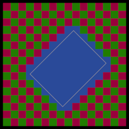
In this graphic, the rectangle of the screen view is represented by the grey rectangle; all cells that the view rectangle intersects are highlighted in blue. You can see that the pattern is not a regular rectangle, but a much more complex shape. In order to render back to front, we need to render this complex shape row by row. Here is a graphic showing rendering order:
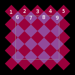
Here you can see some of the squares numbered. This is the drawing order. (The numbering should continue down the whole sequence, but I'm lazy.) If drawn in this order the cells should be drawn with basically correct overlap, as long as the constraints of the system are maintained, as far as object sorting, etc... There are probably going to still be a few edge-cases; this comes with the territory, and most of those can be handled through the collision system, by keeping objects far enough from walls and other solid things so that weird overlap doesn't occur.
Despite the seeming complexity of drawing rows like this, it's actually pretty easy. You can calculate the coordinates of the upper left corner of the chunk by reverse-projecting the upper-left corner of the viewport into World Space. You can calculate the number of columns and rows to draw similarly by dividing the size of the viewport by the on-screen size of a cell. Here, the Height of a cell comes into play, since you need to extend the viewport down to accommodate. You need to draw an arbitrary number of rows below the bottom edge of the viewport, to account for tall objects that might be visible on-screen even though the floor of the cell they lie in might not be. You also need to pad the top and sides by one cell in each direction to account for partially visible cells. But once you have constructed your suitably padded bounds, it becomes a simple matter of iterating the rows.
You start from the top row, which is an Even row. If the number of Nodes you need to draw across the screen (Screen Width / (NodeSize*4)) is NumNodes, then on Even rows you need to draw NumNodes+1 nodes, whereas on odd rows you draw NumNodes cells. (You can see in the image that the rows alternate in length). To advance along a row by one cell, you add 1 to cellx and subtract 1 from cell y. To advance to the next row from an even row, you add 1 to x; to advance to the next row from an odd row, you add 1 to y. And that's basically it. Here is an excerpt from the IsometricMap::draw() method, the part that renders all of the floors:
[spoiler]
void IsometricMap::draw(sf::RenderWindow *win)
{
    // Set view
    sf::View view=win->GetView();
    // Reverse project center
    sf::Vector2f center=WorldToScreen(sf::Vector2f(m_centerx,m_centery));
    view.SetCenter(center);
    win->SetView(view);

    // Reverse-project top-left corner
    sf::Vector2f viewsize=view.GetSize();
    sf::Vector2f topleft=ScreenToWorld(sf::Vector2f(center.x-viewsize.x/2.0f, center.y-viewsize.y/2.0f));
    int sx=(int)(topleft.x/(float)m_nodesize);
    int sy=(int)(topleft.y/(float)m_nodesize);

    // Move start location up and left two nodes to get a little padding. (subtract 2 from sx
    sx-=2;

    // Calculate how many nodes across to draw
    // A node's total width on-screen is calculated as 4*nodesize
    int num_nodes_across=(int)viewsize.x / (m_nodesize*4) + 4; // Pad out the end by drawing 4 extra nodes

    // Calculate how many rows to draw
    // A node's total height on screen is calculated as 2*nodesize. Also, need to fudge it
    // a little bit by adding a value that approximates the maximum cell height to the size of the
    // viewport.
    int num_rows=(((int)viewsize.y+512) / (m_nodesize*2))*2;

    // Update lighting
    m_lightmap.updateRegion(sx,sy,num_nodes_across,num_rows);

    // Drawing proceeds as thus:
    // We begin at some starting node and proceed across the row. At each step, we increment x and decrement y
    // to move to the next node.
    // When a row is done, we move to the next row. This is done by:
    // If the current row is "even", then we move to the next row by incrementing x. If the current row is odd, we
    // move to the next row by incrementing y instead.
    // On even rows, we draw num_nodes+1 nodes, else we draw num_nodes nodes.
    int rowincx=1, rowincy=0;
    int drawnodes=num_nodes_across+1;

    int nodex=sx, nodey=sy;
    for(int row=0; row    {
        if (row & 1)
        {
            // Odd row
            rowincx=0;
            rowincy=1;
            drawnodes=num_nodes_across;
        }
        else
        {
            rowincx=1;
            rowincy=0;
            drawnodes=num_nodes_across+1;
        }


        for(int node=0; node        {
            // Calculate cell coords
            int cellx=nodex+node;
            int celly=nodey-node;
            if(cellx>=0 && cellx=0 && celly            {
                sf::Color color=m_lightmap.getLightValue(cellx,celly);
                m_nodes[celly*m_width+cellx].drawFloors(win,color);
            }
        }

        nodex=nodex+rowincx;
        nodey=nodey+rowincy;
    }
[/spoiler]
This excerpt does a number of things besides just drawing. A map has a specific center specified as an (x,y) coordinate. The center of the map corresponds to the point, in World Space, that aligns with the center of the screen. By changing the center, you can scroll the map. The drawing code presented takes the current View of the passed RenderWindow and uses the dimensions of it, as well as the map center, to calculate all of the parameters necessary for drawing. It also calculates the new Screen Space view necessary to draw the requisite piece of map, centering it upon the map center point. Once the view is set, the rows and columns of nodes in the visible chunk are iterated as described above. This iteration process is actually performed 2 times: once for the floor lists, and once for objects, roofs and walls. A variation of it is also performed before the drawing calls, in order to update the lighting of the visible region. And while we are on the topic of lighting...
[page]
Lighting the World
Isometric games quite frequenly come in RPG varieties, and RPGs like to have lots of caves and dungeons full of darkness and death to play in. So in order to simulate these dark environments we need a lighting system. Presented here is a very simple grid-based lighting system. This system calculates light values per-cell, so the lighting is blocky and very, very retro. The system can be modified fairly easily enough to light the corners of cells, rather than the centers, and by assigning a color value per cell corner, you can achieve smoother lighting across cells; however, SFML as of the latest snapshot still doesn't allow more than a single color per Sprite; perhaps that will change in future iterations of the library. But for now, without performing heavy modifications of the library or without stepping outside of SFML and into OpenGL, we are kind of stuck with one color per sprite, and that means retro lighting.
(Note: SFML does provide a Shader class, that could be leveraged to implement better lighting. I'm working on a system for that even as we speak, though I probably won't discuss it in this article. Maybe in another. The thing is, sf::Shader has higher base requirements, including fragment shader support. But if you want to support it, coolio. You can do some cool stuff with shader-based lighting in a 2D.)
The lighting in this system is simple. It supports static lighting (light that doesn't change, you can set it during map construction and forget about it) and dynamic lighting (lights that move, more expensive than static, but can change position). Two buffers are allocated, one to hold static lighting information, and one to hold the final calculated lights. Also, the light map class maintains an std::list of dynamic lights. Lights are requested and released from the light map class by objects that require them. Here is the lightmap class:
[spoiler]
struct DynamicLight
{
    DynamicLight() : m_position(0,0), m_color(0,0,0), m_radius(0){}
    ~DynamicLight(){}

    void setColor(float r, float g, float b){m_color=sf::Vector3f(r,g,b);}
    void setRadius(float rad){m_radius=rad;}
    void setPosition(float x, float y){m_position=sf::Vector2f(x,y);}

    bool operator==(const DynamicLight &rhs) const
    {
        if(this == &rhs) return true;
        return false;
    }

    sf::Vector2f m_position;
    sf::Vector3f m_color;
    float m_radius;
};


class LightMap
{
    public:
    LightMap(int w, int h, int nodesize);
    ~LightMap();

    void resize(int w, int h);
    void clearStatic();
    void clearDynamic();
    void updateRegion(int sx, int sy, int num_nodes, int num_rows);
    DynamicLight *requestLight();
    void releaseLight(DynamicLight *light);
    sf::Color getLightValue(int x, int y);
    void setAmbient(float r, float g, float b);

    void addStaticLightCell(int x, int y, float r, float g, float b);
    void addStaticLightRadius(float x, float y, float r, float g, float b, float radius);

    protected:
    std::vector m_static;
    std::vector m_final;
    std::list m_lights;
    sf::Vector3f m_ambient;
    int m_width, m_height, m_nodesize;
};
[/spoiler]
As you can see, a DynamicLight is simply a struct containing a position, a radius, and a color. The static light buffer and final light buffer are both std::vectors of sf::Vector3. You'll notice I use Vector3f instead of sf::Color. I have a very good reason for this.
By using Vector3f, I can have negative light. Negative light is useful for creating things like Spells of Darkness, magically darkened areas, etc... By setting a light pool with negative values, light is actually subtracted from the scene. The method getLightValue will obtain a sf::Color for a given cell; in this case, all the ambient, static and dynamic values for the cell are summed, then clamped to [0,1] before conversion to sf::Color. This type of lighting can be very useful. Your player read a scroll of Permanent Darkness? Simply have it call addStaticLightRadius with a negative color to subtract light from the scene centered at the casting point.
In the inner loop of the map draw routine, the light map is called to obtain a Color for each cell, and the color is passed to the cell drawing routines. The objects that are drawn use this light value to color themselves. And here is where we find the use of the m_uselighting parameter we inserted into the IsometricMapSprite class. Some objects are shaded according to the light value of the cell, while others (luminescent objects, particles, etc...) are not. This flag can be set or cleared to enable or disable use of lighting on a per-sprite basis. Sprites that do not use lighting can be colored using Sprite::SetColor, whereas sprites that do use lighting are colored by the cell lighting instead.
Now, this lighting system is very simple, and doesn't take into account things that block light and cast shadows.
Now, that was a pretty rough overview of how the system works, so let's talk a little about map management and the responsibilities of code that uses this system.
[page]
Isometric Map Management
Here is the class declaration for IsometricMap:
[spoiler]
class IsometricMap
{
    public:
    IsometricMap(int w, int h, int nodesize);
    ~IsometricMap();

    void resize(int w, int h);
    void clear();

    void insertSprite(IsometricMapSprite *s);
    void removeSprite(IsometricMapSprite *s);
    void draw(sf::RenderWindow *win);

    sf::Vector2f projectMouseCoords(int mx, int my, sf::RenderWindow *win);

    void addLeftWall(int x, int y, std::string &name); // Set a left wall piece
    void addRightWall(int x, int y, std::string &name);
    void addFloor(int x, int y, std::string &name);
    void addRoof(int x, int y, std::string &name, float height);

    void setCenter(float x, float y) {m_centerx=x; m_centery=y;}

    LightMap *getLightMap(){return &m_lightmap;}


    protected:
    std::vector m_nodes;
    int m_width, m_height;
    int m_nodesize;
    float m_centerx, m_centery;
    std::list m_mappieces;
    ImageManager m_mapimages;
    LightMap m_lightmap;

};
[/spoiler]
A couple things of interest here. First of all, in the protected section of the class declaration, you can see the line ImageManager m_mapimages. This is a simple class that tracks sf::Images. You can request an image by filename from the manager, and if the image is already loaded it will merely return a pointer to the existing instance of the image, rather than allowing multiple copies of the same image to bloat memory usage. There is also a list of IsometricMapSprites called m_mappieces. This is a convenient means of providing a container to own specific instances of IsometricMapSprites that are used solely by the map: namely, wall, floor and roof pieces.
The class provides methods for resizing, clearing, drawing, etc... There is a method to set the center point, a method to get a pointer to the intrinsic lightmap, in order to effect lighting processes. There is a function, projectMouseCoords, that will take a set of mouse coordinates and convert them into World Space. Note that this method projects Screen Space coords onto the Z=0 plane of World Space; other math would be necessary if you require projection onto other planes of World Space.
Now, of particular interest here are the methods addLeftWall, addRightWall, addFloor, addRoof. These methods are given a coordinate pair (in cell coordinates, not world coords) and the name of the graphic file to load. addRoof also takes a height parameter, used to set how high above ground level the roof should be placed. These functions will instance an IsometricMapSprite and insert it into the m_mappieces list, then request the specified Image from the image manager. Various data are set, including origin points for the Sprite (see sf::Sprite::SetOrigin) and World Space coordinates, then the sprite is added to the appropriate cell. An entire map can be built (well, the static geometry, at least) via these calls. Clearing the map will delete these instanced lists.
Another item of interest are the insertSprite and removeSprite calls. These are of importance for dynamic objects that move around, inserting and removing them from their appropriate cell buckets. It is important to call removeSprite before a sprite's position is updated, then call insertSprite again to insert it at the new position. This sort of micromanagement could be handled more automatically with a little work, but I don't really find it necessary. Just remember to remove and insert any time you update an object's position, and things should be groovy.
With a bit of extra work, you could tweak the system to allow multiple maps, managed by a MapChunk type of interface, in order to implement a dynamic streaming system, wherein map chunks are streamed in and out of memory as the center moves. There are a couple sticky spots in this case (the lighting system being one of them; lights would have a tendency to not cross chunk boundaries, without additional code being written) but with some elbow grease they could be ironed out. The map drawing and light updating would have to be moved out of the IsometricMap and into the interface that handles multiple maps.
I was going to go into an explanation of creating artwork for a game like this, but this beast is long enough as it is. Maybe in another post. If you are curious as to the manner and layout of the graphics, all of the graphics for the demo are included in the project archive as .TGA format images. Open them up to see how they are constructed as far as layouts, alpha channels, etc... Also,the code for generating the map is included in the project so you can examine it to see how the map is built up. The avatar sprite is just a single animation frame taken from one of the enemies in my current game, Goblinson Crusoe. In reality, he would be an animated sprite with different facing directions. But that, too, is a topic for another day.
Good luck, and have fun.