Introduction
While working on a project for school, I found it necessary to perform a collision check between sprites that had been translated and rotated. I wanted to use bounding boxes because a per-pixel check was time consuming and unnecessary. After a couple of days of research I managed to work out an efficient solution using the separating axis theorem. After explaining my method to classmates and a few lab technicians, I realized that the game development community could benefit from a clear and thorough explanation of the process. Knowledge of linear algebra, specifically vector math, is useful but not necessary for understanding this article.
Separating Axis Theorem
The separating axis theorem states that for a pair of convex polygons that are not in a state of collision there exists an axis perpendicular to an edge of one of the polygons that has no overlap between the projected vertices of the two polygons. Essentially, what this means is that if we project the vertices of the two polygons that we are testing onto each axis that is perpendicular to the edges of each polygon and we detect an overlap on each polygon there is a collision, if even one axis shows no overlap then a collision is impossible. This solution works for any collision possibility, even the dreaded cross collision.
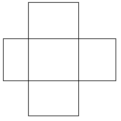 Figure 1. Cross Collision
Setting Up
Before we dive into the collision algorithm itself, there are a few prerequisites for this particular method. Firstly, although the separating axis theorem can be used to check for collisions between any convex polygons, rectangles are the normal collision method in 2D, so I will assume that you are using rectangles. Additionally, I will assume that you can convert your rectangles into a structure with four vectors, each representing a corner, and labeled or organized in such a way that you can tell which corner is which (specifically, we need to be able to identify which corners are adjacent - if the upper-left corner has been rotated until it is on the bottom of the rectangle that's fine, just so long as it remains connected by an edge to the corners labeled upper-right and lower-left.).
The Method
The problem with checking for collision between two rotated rectangles is really a matter of being able to decide when they're not colliding. The simple intersection test used by the Microsoft InteresectRect() function will check if the minimum and maximum x and y values of rectangle B are within the minimum and maximum x and y values of rectangle A. This method works fine for axis-aligned rectangles, but when dealing with rotated rectangles we need something a little more complex.
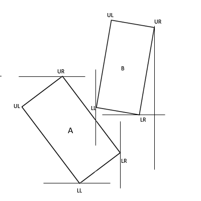 Figure 2. Standard Bounds-based Collision Check
As you can see, the minimum x value of B lies within the space defined by the minimum and maximum x values of A. Additionally, the minimum y value of B lies within the space defined by the minimum and maximum y values of A. With simple bounds based collision detection this would register as a collision, when it clearly is not.
Step 1
The first step in this method is to determine the axes that we will be projecting our vertices onto. The separating axis theorem states that we must have an axis that is perpendicular to each of the edges of our two polygons.
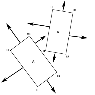 Figure 3. The Eight Perpendicular Axes
As you can see, we end up with eight axes. You should also immediately see the benefits of using rectangles. Firstly, each edge has an opposite edge which shares an identical axis, we can take advantage of this to lower the number of axes that need checked to four. Secondly, the angle that exists between any two adjacent edges on a rectangle is 90 degrees. As such, for any edge of a rectangle, both of the adjacent edges are perpendicular to it. This means that we can calculate our four axes to be as such:
Axis1.x = A.UR.x - A.UL.x
Axis1.y = A.UR.y - A.UL.y
Axis2.x = A.UR.x - A.LR.x
Axis2.y = A.UR.y - A.LR.y
Axis3.x = B.UL.x - B.LL.x
Axis3.y = B.UL.y - B.LL.y
Axis4.x = B.UL.x - B.UR.x
Axis4.y = B.UL.y - B.UR.y
Meaning that Axis 1 is the resultant vector of the upper-right corner of A minus the upper-left corner of A and so on. This gives us four axes, each of which is perpendicular to two opposite edges of one of the rectangles, meaning that for each edge we have an axis that is perpendicular to it.
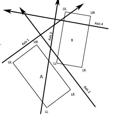 Figure 4. Our Four Axes
Step 2
The next step is to project the vectors representing the four corners of each rectangle onto each of the axes. If you know how to do matrix projections then you should have no problem doing this. Ifyou understand vectors, but have forgotten how to do projections, then here is the equation for the projection of rectangle A's upper-right corner onto Axis 1:
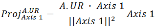
Here is the equation expanded out into scalar math and simplified:
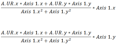
It is important to note that the only difference between these two equations is that we're multiplying by Axis 1's x coordinate at the end of the first equation and we're multiplying by Axis 1's y coordinate at the end of the second equation. That will give you the x and y coordinates of A.UR projected onto Axis 1. As an example, let's pretend that A.UR isat location (2, 6) and Axis 1 is represented by the vector (3, 4):
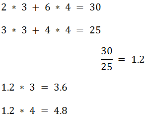
Therefore, in this example, the x coordinate of A.UR projected onto Axis 1 is 3.6 and the y coordinate is 4.8.
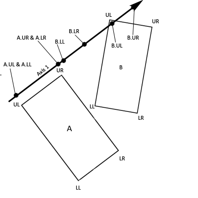 Figure 5. Vectors Projected Onto Axis 1
Step 3
The third step in this algorithm is to calculate scalar values that will allow us to identify the maximum and minimum projected vectors for each of the rectangles. While it might seem natural to use the norm (length) of the vectors, this won't work as coordinates with negative values will return a positive scalar value. The simplest and cheapest solution is to take the dot product of each of the vectors and the axis. This will give us an essentially meaningless scalar value, however, this value will be indicative of the vector's position on the axis. To use our above example:

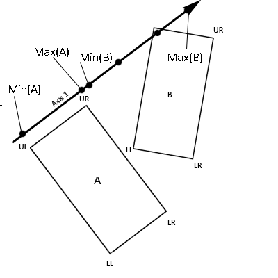 Figure 6. The minimum and maximum scalar values
Step 4
Now identify the maximum and minimum scalar values (the ones that we just calculated) for rectangle A and rectangle B. If the minimum scalar value of B is less than or equal to the maximum scalar value of A and the maximum scalar value of B is greater than or equal to the minimum scalar value of A then our objects overlap when projected onto this axis.
There is an error in the below image regarding Min(A). Please refer to the text above for the correct equation
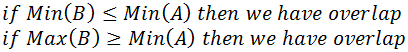
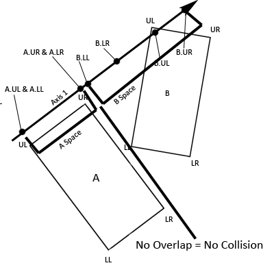 Figure 7. No Overlap = No Collision
Repeat
Repeat steps 2, 3, and 4 for each of the axes. If all of the axes show an overlap then there is a collision, if even one of the axes shows no overlap then there is no collision.
Optimizations
There are a few things that can be done to optimize this algorithm:
- You can and should stop checking for collision the instant you find an axis where the rectangles don't overlap. Remember, the separating axis theorem says that if two polygons arecolliding all axes that are perpendicular to the edges of the polygons will show an overlap. Meaning that, if one axis shows no overlap, then collision is not possible and you should opt outto prevent unnecessary math.
- It can really pay off to transform rectangle B into rectangle A's local space. In order to do this, you should maintain these rectangles in local space and then transform rectangle B intoworld space and then by the inverse of rectangle A's world space transform to put rectangle B into rectangle A's local space. Then, translate both rectangles equally so that rectangle Ais centered about the x and y axes. This means that two of the four axes that you need to project vectors onto are the unit (x and y) axes. Simply check for overlap between the x values of thecorners of both rectangles and between the y values of the corners of both rectangles. With this solution you only have to actually project the vectors onto arbitrary axes twice, instead of fourtimes.
 Figure 8. Rectangles A and B in world space
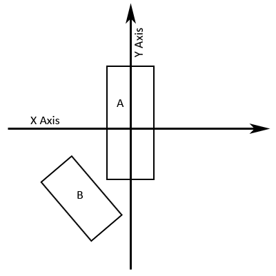 Figure 9. Rectangles A and B Transformed Into A's Local Space
- It can be wise to utilize a radius that completely encompasses the rectangle. If the distance between the centers of rectangles A and B is greater than the radius of A and B added together thenthere cannot possibly be a collision and it is unnecessary to use the separating axis theorem.


Hi there :D
Nice tuturial