Introduction
Silhouette rendering is one of the algorithms that has always interested me. There are many different reasons to try to render silhouettes such as accentuating model details, cartoon style highlighting, and edge detection in various non-photorealistic rendering techniques. There are equally many different methods that have been developed over the years to achieve these rendering effects. These methods are used in a variety of rendering applications, both in realtime as well as offline rendering.
While implementing some of the more popular methods, I found that many of them either did not produce the quality of silhouette that was desired, weren't fast enough for realtime use on older hardware, or were very difficult to implement. So I decided to design a method that could run at interactive frame rates with good image quality and that would not require an excessive amount of software to implement.
This article proposes the resulting method for rendering fast silhouettes, creases, and ridges on shader model 1.1 hardware at interactive frame rates for low to moderately complex geometry. The algorithm and implementation targets static polygonal models, but a description is provided of what changes are needed to use this method on dynamic models as well. A reference implementation is provided as a DirectX 9 HLSL effect file. The reference effect file is provided with the article and may be used in whatever manner you desire.
Silhouette rendering
Before examining the algorithms, we first have to define what exactly we are trying to render and what characteristics the algorithm should support. Silhouette rendering algorithms typically focus on three different types of geometric features of polygonal models: outlines, ridges, and creases.
The outline of a model can be defined as the list of all of the edges between front facing and back facing polygons in the current camera view. Because determining which polygons are front facing and which are back facing polygons is dependent on the camera location, it is necessary to recalculate this list any time the model or the camera moves. A typical application for highlighting the outline of a model is cartoon rendering. It is usually more aesthetically pleasing to view a cell-shaded image with outlines instead of without them.
Ridges and creases of a model are very similar in nature to one another. When a polygon edge connects two triangles that are at a large angle to one another it is usually an important feature of the model. This would be a sharp edge or a very steep valley. The threshold angle that is considered to constitute an important edge is usually adjustable for both ridges and valleys, and depends on how the application is using the ridges and valleys.
Algorithm Overview
I wanted to make sure the algorithm was fast and relatively simple to implement. The ideal method would require zero pre-processing time and still not require extensive runtime processing. Due to the nature of the problem I ended up settling on a mixture of both pre-processing and runtime processing. The overview of the algorithm is to create a special set of geometry based off of the polygonal model that contains the needed edge information as a pre-process. This 'edge' triangle mesh is then used to detect and render each of the special edges that we defined above in the vertex shader at runtime.
So the first step in the process is to generate an edge mesh. The edge mesh is a generated from the original polygonal mesh that we want to draw silhouette edges for. The vertices of our edge mesh will contain the following elements:
struct vertex
{
    float3 position : POSITION;
    float3 normal   : NORMAL;
    float3 tangent  : TANGENT;
    float  ridge    : TEXCOORD0;
};
The position is provided as a three-component point in space. The normal and tangent vectors are also three-component vectors, and an additional single-component texture coordinate is also stored. For each triangle edge that is shared by two triangles, we generate four vertices and two triangles. Two of the vertices are associated with one triangle face and the other two vertices are associated with the other triangle face that shares the edge. Figure 1 shows the orientation of the new geometry with respect to the original models edge.
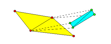
Figure 1: Edge Geometry Orientation
Each of these vertices is given a position equal to the vertex of the original model - the two new triangles are initially degenerate. This means that the green vertices in Figure 1 would be positioned right on top of the red vertices that they are generated from (indicated by the dashed line). The vertex positions are later modified so that the edge mesh triangles only appear where a special edge should be seen.
The new vertices must also store a vertex normal vector and a vertex tangent vector. The vertex normal vector is the vertex's triangle face normal and the tangent vector is the face normal of the other triangle that shares this edge. Figure 2 shows an edge-on view of the original polygonal mesh on the left hand side, and the new edge geometry (green vertices) on the right hand side.
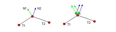
Figure 1: Edge Geometry Normal And Tangent Vectors
So the edge mesh vertices on the T1 face side of the edge will store N1 as its normal vector, and will store N2 as its tangent vector. Conversely, the edge mesh vertices on the T2 face side of the edge will store N2 as its vertex normal and N1 as its vertex tangent vector. It is important to note this distinction between the vertex normal vector and the vertex tangent vector as these vectors are used later on in the rendering process.
The ridges and valleys of a static model are always ridges and valleys - they don't change at runtime. I take advantage of this and pre-process this information. The single-component texture coordinate, named the vertex 'ridge', is used to specify if that vertex is on a ridge or valley. If the vertices are generated from a ridge or valley edge, then a 1.0 is stored, otherwise a 0.0 is stored. Again, this value is used later on in the rendering process.
Rendering Implementation
With our per-vertex information defined, we can now render the edge mesh. The overall concept is to use the new per-vertex data that we just defined to determine if the edge geometry should be visible or not. If it should be visible, then we will displace the proper vertices to set the correct outline thickness. If it should not be visible, then we discard the geometry using the alpha test.
All of this work is done in the vertex shader. Since the edges of a polygon are always line segments, there is really no reason to perform the operation per-pixel - the calculations can be made per-vertex and the results will be linearly interpolated without any loss in image quality. This makes the overall algorithm quite fast since it doesn't operate per-pixel. In addition, working in the vertex shader makes the algorithm capable of executing on older hardware.
Now we will look in detail at what the vertex shader is going to be calculating. The vertex shader calculations are all going to be performed in world space, so the first task is to convert the object space vertex data into world space. Then we calculate the vector from the vertex to the camera in world space. It is important to note that the eye vector is not normalized:
float4 WorldPos = mul( float4(IN.position, 1), ModelWorld );
float3 P = WorldPos.xyz;

float3 N = mul(IN.normal, (float3x3)ModelWorld);
float3 T = mul(IN.tangent, (float3x3)ModelWorld);
float3 E = P - CamPosition.xyz;
Next we initialize the vertex output color to all 0's. This includes the alpha channel of the color - this will be important as we carry out the computations:
OUT.color = 0;
Now we calculate the dot product of the eye vector with the vertex normal vector, as well as the dot product of the eye vector with the vertex tangent vector. The result of both of these calculations will be positive if the eye vector is facing the same direction as the other vector, indicating that the polygon face that the vector was taken from is forward facing. Conversely, if the result is negative, it indicates that the polygon face is currently backward facing:
float EdotN = dot(E,N);
float EdotT = dot(E,T);
Next we calculate a scaling factor to determine how much to displace the vertices by if they should be visible. This is essentially just based on the distance from the camera, and can be modified to suit the application.
float extend = 0.1 * (length(E)/75);
Now we calculate the displacement of the vertex under the assumption that it will be visible. The vertex is displaced along its normal vector by the distance scaling factor that we calculated in the last step. This position is in model space since it uses the vertex's input position and normal vector. This has the effect of pushing the edge geometry diagonally from the actual model edge (see the demo for better clarification).
float3 newPos = IN.position + IN.normal * extend;
Currently, the vertices are displaced along their normal vectors and when viewed from a distance they would appear to be a wireframe overlay over the original mesh. However, we only want to display the silhouette edges, ridges, and valleys. This is why the alpha channel was initialized to zero - it will be used to indicate what parts of the edge geometry should be rendered.
The first test is whether or not the edge is a silhouette. This can be determined if the two polygons that share that edge are facing opposite direction with respect to the camera. If one polygon is back facing and the other is forward facing, then the edge is on the silhouette. We test this by multiplying the two dot product results from earlier and testing to see if the result is negative:
if ( ( EdotN * EdotT ) < 0 )    // silhouette detection
{
    OUT.color.a = 1;        // make this visible
    if ( EdotN > 0 )        // extend only the front facing vertices
    {
        newPos = IN.position - IN.normal * extend;
    }
}
Also, if the edge is a silhouette, we extend the vertex in the opposite direction to make them more visible for relatively smooth geometry. Now, if the pre-computations say that the edge is a ridge or a valley, then we set the alpha channel to 1 by setting it equal to the vertex ridge value:
OUT.color.a += IN.ridge;   // set visibility for ridges
                           // and valleys (pre-computed value)
Finally we transform the displaced model space vertex position into clip space with a standard model-view-perspective matrix and return the result:
OUT.position = mul( float4( newPos, 1), Transform );

return OUT;
Now that the vertex has been output, the pixel shader simply passes the vertex color through to the frame buffer:
OUT.color = IN.color;
However, we enable the alpha test with an alpha reference of 0x01. This only writes the pixels produced by vertices that we have set an alpha value greater than zero:
AlphaTestEnable = true;
AlphaRef = 0x00000001;
AlphaFunc = Greater;
This effectively eliminates any geometry that we don't want the viewer to see. The overall process can be somewhat difficult to visualize, so I am including a demonstration application that you can experiment with. The application loads a Milkshape3D file, performs the preprocessing step, and then renders the original model with the edge mesh rendered over the top of it. The application will allow you to rotate around the object with the mouse, and you can zoom in and out with the mouse wheel. Escape will exit the program.
Please feel free to try out your own models with the demo to see how they look. Simply place your model in the Data/Models sub-directory and name it Edge_Mesh.ms3d and then run the executable. The threshold ridge and valley angle is about 90 degrees. To get your input models working properly with the demo, it is helpful to 'unweld' all of the vertices in Milkshape. This is simply a limitation of the preprocessing code that I wrote - it would likely be done at model load time in a real application.
To get this algorithm working on dynamic models, the vertex normal and tangent vectors would have to be updated whenever the model is modified. In addition, the pre-processed vertex ridge value would have to be calculated in the vertex shader. This would be done with a simple dot product of the vertex normal and tangent vectors, and then a comparison would have to be made based on the resulting value. In either case, this method should still perform well on dynamic models since it only operates on vertices.
Conclusion
Hopefully this silhouette rendering method is useful to the community in some way. I have found that it is significantly faster and easier to implement than previously devised methods. If you can think of optimizations or further applications for the algorithm, I would be more than happy to hear your thoughts. Please PM me on the Gamedev.net messenger to start a discussion.