The proposed terrain system will manage the physical information of the track, building an internal data structure and applying a spline algorithm to get an smoothed continous surface.
The physical data structure is not made of triangles or polygons, and no raycasting or polygon collision is performed in the game, which leads to good performance, low memory cost and configurable continuous smoothness (no sharp edges between polygons).
The physical data is generated in a preprocess out of the game, and then saved to a binary file. The track information can be taken from the graphical circuit, raycasting at the control point positions.
To keep the explanation simple, the data structure can be a plain c-style array with the control point positions : Point3D ctlPoints[NumRows][NumColumns] , where every control point position is stored in the array at their column-row slot.
 This system has been succesfully implemented and tested on a real case: a racing car videogame for the Wii, with 12 fast (about 110 km/h) cars on a track with bumps, cambers, crosses of different levels ... The 12 cars together consumed 1.53% of the CPU process (in the worst case) to obtain information of height, normal and tangent from the terrain, and 0.2% more on knowing its distances to the barriers.
Please note that there are multiple possible implementations, variations and optimizations, as each game should have its own version and applications. The basis is a data structure with spatially-organized control points along the route and a spline algorithm to get a smoothed surface from them.
Features
- It doesn't use polygons or triangles, and no raycasting or polygon detection is performed in real-time.
- It allows curves, hills (up-down), concaves (half-pipe, etc ...), all types of camber ...
- It's not a heightmap, although it shares some characteristics . Some differences:
-
- Supports various altitudes. Some paths may cross with others at different heights ...
- The checkpoints follow the path, so we just store the terrain information that we need, not the entire "rectangle" that covers the circuit - as a heightmap would do.
- Very little memory needed, much less than with polygons or triangles. The amount of memory needed depends on the control point density configured. This density will not affect the continuous smoothness of the terrain, so it is possible for certain titles to have a very low density of control points.
- Very good performance. The performace remains constant, no matter the circuit size or the control point density.
- The collision system takes advantage of the predictable movement of the cars through the track, as they use to move "linealy" and continuosly , and the track data is stored organized. It is not efficient for aleatory movements (for instance, if a car is suddenly placed in the middle of a circuit).
- The data structure and calculations can be reused for many other gameplay needs:
-
- barriers.
- tracking waypoints.
- race car positions
- Can be used as a partition space system: collision tests only if you're in the same area, cullings graphics, LODS, optimizations ...
- It gives us the ground as a continuous curved surface, regardless of the density of control points we use.
- Smoothing the polygonal terrain, we separate the physics from the graphics. Depending on the control points density that we set, we will have more softness (if less control points) or more fit to the polygonal track (with more control points).
Setting a density of one control point row each 3-5 meters, the physics will fit quite well to the poligonal track.
Setting a density of one control point row each 50 meters, the physic track will be super-smoothed and very low memory consuming, the drawback being that you must build (or at least modify) a custom graphical track to avoid graphical-physics differences .
Implementation
We built the physics data based on already made graphical track meshes that didn?t have any specific optimization or programming-friendly feature, and we didn?t have the time to reorganize these graphic assets - which was a constraint. There are 2 different phases :
First, a precalculation to make an specific data structure from the graphics. It is done out of the game, and several physic files are generated .
To end, in the game, the data files are loaded and, at real time, the height and normal is calculated for an specific track position.
Real-time calculations
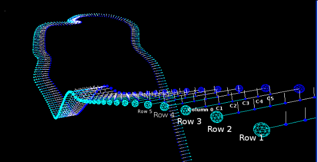
The first step is to calculate where the car is, related to the track control points : lengthwise ( rows ) and widthwise ( column ). For example:
- lengthwise : the car is 0.2 of row2 and and 0.8 of row3.
- widthwise : the car is 0.3 of column3 and 0.7 of column4.
Calculating the row coordinates of 12 cars consumed 0.41%, and calculating the column coordinates of 12 cars consumed 0.38% of CPU process.
The last step is to get the height and normal of the track at this row and column coordinates.
From the calculations already made (row and column coordinates) we know the 16 control points around, and the distance to the next column and row.
It is time now to get the smooth, continous curved surface from the 16 control points. For this we must use an algorithm for curved surfaces, such as Catmull-Rom.
Given a set of n points, catmull-Rom splines specifies a curve that will pass through all of the control points. For instance, the following function can be used to get the point position of the curve that is between p1 and p2 , and is 0.2 distance of p1 ( so 0.8 of p2 ) :
Point3D CatmullRom(Point3D a, Point3D b, Point3D c, Point3D d, float i) { return a * ((-i + 2) * i - 1) * i * 0.5f + b * (((3 * i - 5) * i) * i + 2) * 0.5f + c * ((-3 * i + 4) * i + 1) * i * 0.5f + d * ((i - 1) * i * i) * 0.5f; } To get the 3D point in the curved surface especified by the 16 control points around us, one option is to do the following : p0= CatmullRom(D0,D1,D2,D3,columnProgress); p1= CatmullRom(C0,C1,C2,C3,columnProgress); p2= CatmullRom(B0,B1,B2,B3,columnProgress); p3= CatmullRom(A0,A1,A2,A3,columnProgress); finalPoint= CatmullRom(p0,p1,p2,p3,rowProgress);
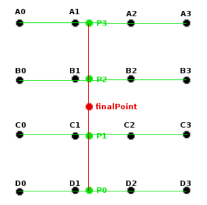 columnProgress (the column coordinates calculated in the last step), signifies the portion of the distance between the column at the left and the column at the right (normalized, between 0 and 1).
rowProgress (the row coordinates calculated in the last step), signifies the portion of the distance between the row before us and the row in front of us (normalized, between 0 and 1) .
finalPoint is the 3d point coordinates of the especified point projected to the curved surface. With this information we know the height of the point to the curved surface .
This calculation, for 12 cars, obtaining the height, normal and tangent of the circuit consumed 0.73% CPU.
Preprocess calculations
The preprocess calculations are done out of the game. One of the basic things the preprocess has to do is to fill the data structure ctlPoints[NumRows][NumColumns] with the projected position of every control point. This data is stored on disk, and the resulting file can be loaded whenever needed into the game. The projection can be done via raycasting to the graphical, polygonal track.
To know where the control points are placed (before the projection), we need logical waypoints placed along the route. They don't need to be accurate, it doesn't matter the distances between them ... These waypoints can be "dummies" in Max, or Maya ...
These waypoints are used to trace a spline (Catmull-Rom) along the route that will be used as a guide to place the control points.
Throughout the continuous curve generated from the waypoints, every x meters we set a row of control points, with the columns placed width-wise perpendicular to the circuit ( transversal to the spline ) .
For each control point (at every row and column) launch a raycast, and the collision point will fill ptosCtl [NumRows] [NumColumns].
Variations
The proposed terrain system has many possible implementations and variations, all based on its internal data structure designed for circuit tracks ( which is the core of the system ). I will expose here some of the many possible variations for the system.
1. First build the smoothed physical track, and then build (or modify) modify the graphic information to fit it
This way you can set a super-smoothed and super-memory-efficient physics track, for instance a density of one control point row each 50 meters and 3 control points per row. This low control point density will make a very smooth and "rounded" track . 10 kilometers of physical track info can be stored in 3(x,y,z) * sizeof(float) * 3 (control points in a row) * 200 (rows in 10.000 meters) bytes = 1800 * (sizeof float ) bytes. It takes about 8 kb to store 10 km of smooth track!
Once the internal physics data is built, the graphic data should be made or modified modified and its vertex projected to the surface spline.
Another positive point is that the different levels of detail of the graphical tracks fits the same physical information, so the different detail levels are consistent to the car collisions.
2. How to set hard bumps, ramps, obstacles and other discontinuities in such a smoothed environment?
Instead of trying to fit every obstacle into the terrain data, it's a good idea to deal with them as "exceptions". There can be several obstacles, power-ups ... and the collision detections can be performed in a "more classical" way, testing against its polygons, triangles, raycasting ...
Both systems will work nicely together, filling the gaps.
3. Use the internal data structure for raycasting, forgetting all about splines and curved surfaces.
The control points can be used to make a polygonal track, and then launch raycastings against its triangles.
The structured internal data can be used to choose wich triangles can be discarded, and which ones should be tested.
The calculations done to get the car position (lengthwise and widthwise the track) are performed to find the triangles that are in this same position.
The control points are stored spacially ordered, so it is a simple task to find the closer triangles to a track position .
This implementation doesn't use any spline algorithm between control points, it's a polygonal method, so it needs a high vertex (control points) density to be smooth enough.
This one is definitely an easier implementation.
References
Bicubic interpolation (GDNet Forums)
Bezier Curves and Surfaces
AI Game Programming wisdom I section 9-1 "Representing a racetrack for the AI, by Gari Biasillo

