The simplest way to do this is to take our static ground rectangle and make it dynamic, resizing it as the camera moves or gets higher in altitude. But this means the rectangle will be much larger than it really needs to be most of the time. In this article, we will look at a more precise method that calculates the exact shape of the camera's intersection with a flat ground plane preventing the need for view frustum culling or screen clipping.
Finding the camera's footprint
In order to use this method, we need to have a camera position and orientation, as well as the dimensions of the viewport and the field-of-view angle.
The first step in the process is to calculate a rectangle that sits in front of the camera, is oriented according to the current orientation of the camera, and has the same width and height as the viewport.
Fig. 1 demonstrates this rectangle.
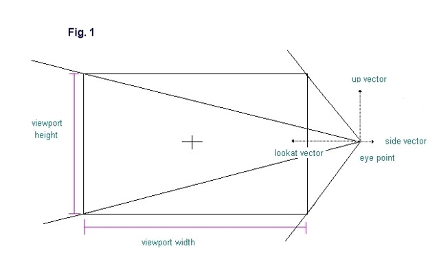 In order to calculate the corner points of the rectangle, we use the "side" and "up" unit vectors of the camera. In the demo, a camera class is used that stores these vectors but they can also be pulled out of the camera matrix if that is how the camera is represented instead. To get the y coordinate of each corner point we multiply the "up" vector by half the height of the viewport and to get the x coordinate we multiply the "side" vector by half the width of the viewport. In order to calculate the z coordinate we must know the "view distance", or the distance along the "lookat" vector at which the frustum has the same dimensions as the viewport. Looking again at Fig. 1, we see that the rectangle that we are trying to create represents a single slice of the camera frustum. This slice can be made at any distance from the camera eye point, but at only one distance will the slice have the same width and height as the viewport. This distance is the "view distance".
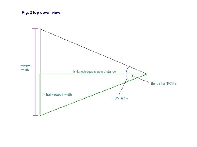
In order to calculate the "view distance" we use a simple formula based on the tangent of the field-of-view angle. In Fig.2 we have defined a triangle, shown in green, where the base, b, has the same length as the "view distance". The height, h, is equal to half the viewport width and is parallel to the "side" vector. Since b bisects the field-of-view angle, then theta is equal to half the field-of-view angle.
Since we know that:
tan( theta ) = h / length of b
then if we solve for length of b we have
length of b = h / tan( theta )
So "view distance" is equal to the length of b, or half viewport width / half fov angle.
 In the demo source code, the "drawHorizon" method of the RendererBase class contains the code for implementing these calculations:
void RendererBase::drawHorizon( QCamera &qcamera, const ViewPort &viewport ) { D3DXVECTOR3 lookAt = qcamera.lookAt(); D3DXVECTOR3 side = qcamera.side(); D3DXVECTOR3 up = qcamera.up(); D3DXVECTOR3 eye = qcamera.eye(); std::vector clippedPts, pts; pts.reserve(4); D3DXVECTOR3 viewC = lookAt * viewport.viewDistance(); float scrHalfW = viewport.screenWidth() * 0.5f; float scrHalfH = viewport.screenHeight() * 0.5f; // UL pts.push_back((up * scrHalfH) + side * (-scrHalfW) + viewC); // UR pts.push_back((up * scrHalfH) + (side * scrHalfW) + viewC); //LR pts.push_back((up * -(scrHalfH)) + (side * scrHalfW) + viewC); //LL pts.push_back((up * -(scrHalfH)) + (side * (-scrHalfW)) + viewC); So now we will have four points contained in a vector and which represent the corners of our rectangle. The next step is to clip this rectangle below a horizontal plane that is parallel to the ground plane (i.e. all points have the same y-coord) and is slightly below the camera eye point. Why does it need to be below the camera eye and not exactly at the same height? This will be explained later but for now let us look at the clipping process. We will use the Cohen-Sutherland algorithm [LaMothe2003] , but pretty much any clipping algorithm will do. The basic idea is to look at each edge in the rectangle one-by-one and check to see if one of three cases is true: both end points are above the plane, both are below the plane, or one is above and the other is below. If both are above, we remove the edge from the list. If both are below we keep it in the list. If one is above, then we move this point down to the clipping plane and keep the other point the same. The rest of the "drawHorizon" method shows how this is done in code: int v1,v2, cp = 0; float x1,y1,z1,x2,y2,z2,newx,newz,m; float ymax = -1.0f; v1=3; for (v2=0; v2 < 4; v2++) { x1 = pts[v1].x; y1 = pts[v1].y; z1 = pts[v1].z; x2 = pts[v2].x; y2 = pts[v2].y; z2 = pts[v2].z; if ((y1 <= ymax) && (y2 <= ymax)) { clippedPts.push_back( pts[v2] ); } else if ((y1 > ymax) && (y2 > ymax)) { // completely above } if ((y1 <= ymax) && (y2 > ymax)) { if (x1 != x2) { m= (y2-y1) / (x2-x1); newx = x1 + ((ymax - y1) / m); } else newx = x1; if (z1 != z2) { m= (y2-y1) / (z2-z1); newz = z1 + ((ymax - y1) / m); } else newz = z1; clippedPts.push_back( D3DXVECTOR3(newx,ymax,newz) ); } if ((y1 > ymax) && (y2 <= ymax)) { if (x1 != x2) { m= (y2-y1) / (x2-x1); newx = x1 + ((ymax - y1) / m); } else newx = x1; if (z1 != z2) { m= (y2-y1) / (z2-z1); newz = z1 + ((ymax - y1) / m); } else newz = z1; clippedPts.push_back( D3DXVECTOR3(newx,ymax,newz) ); clippedPts.push_back( pts[v2] ); } v1=v2; } cp = clippedPts.size(); if (cp == 0) { return; } We now have a vector containing a set of points which represent our clipped rectangle. This vector can contain anywhere from zero to five points depending on how the camera is oriented. Fig. 3 shows a diagram of this rectangle.
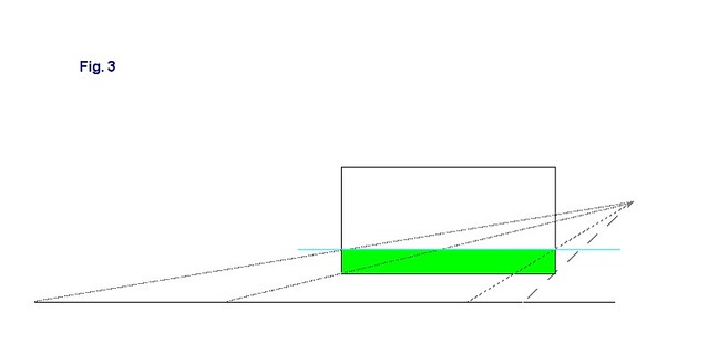 The green area is our clipped rectangle, which represents the horizon image. The blue horizontal line represents our clipping plane. You can now see that if we draw lines from the camera eye to each of the rectangle corners, and then extend these lines until they intersect the ground plane, we will end up with a set of points which represent the camera's footprint on the ground. This is why we needed to make the clipping plane slightly below our camera, because if it were at the same height, the top two lines would be parallel to the ground and would extend forever, never intersecting the ground. In the clipping code above, "yMax" represents the distance between the camera eye point and the clipping plane. In the demo, this is set to -1.0 but it can be any number less than zero. It is just a matter of visual preference, the further below the camera the clipping plane is, the further down in the viewport the horizon image will appear. Another option would be to define an epsilon value in our clipping code that would represent the minimum y-distance any point can be from the clipping plane. Then we would no longer need to move the clipping plane below the camera.
The code for extending the edges and converting into world space is shown below:
for (unsigned int i=0; i < cp; i++) { D3DXVec3Normalize( &footPrintVertex, &clippedPts ); scale = fabs(footPrintVertex.y == 0 ? 0 : eye.y / footPrintVertex.y); footPrintVertex *= scale; footPrintVertex.x += eye.x; footPrintVertex.y += eye.y; footPrintVertex.z += eye.z; .... .... } We simply go through each point in our vector of clipped points and normalize them. Then we scale each one by the height of the camera. Then we add the position of the camera eye and we now have our camera footprint in world space coordinates! Now all we have to do is render them as a triangle fan.
Rendering the camera's footprint
In order to render our camera footprint, we need to consider what kind of projection we are using in our transformation pipeline.
If we are using a perspective projection, it is quite simple to render the footprint since it is already in world space coordinates. We simply pass these points into the API as a triangle fan and voila, we now have a horizon on screen. Of course, we should probably add textures to the horizon so we can have some ground detail which will give us a sense of altitude. This is also quite easy since all we have to do is scale the x and z coordinates of our points and we will get our tiled texture coordinates. This is shown in the "renderCameraFootprint" method of the PerspectiveRenderer class, included in the demo:
geometryVertices.position = footPrintVertex; geometryVertices.tu = footPrintVertex.x / 200.0f; geometryVertices.tv = footPrintVertex.z / 200.0f; geometryVertices.ts = footPrintVertex.x / 15000.0f; geometryVertices.tt = footPrintVertex.z / 15000.0f; The perspective render version can be seen in the viPerspective.exe application. We will use two textures to render the ground plane. This is because the higher you go, the smaller the texture tiles become until they are almost not visible. The second texture will be blended with the first and will have a larger tile size so it will become more visible as we go higher, providing new detail at higher altitudes. Now, if we are working in an environment where we will not be using any kind of a projection matrix, we will have to do a little more work since our footprint is in three-dimensional world coordinates and we need it to be in two-dimensional screen coordinates. Fortunately, the calculations are pretty easy, we just add perspective to our coordinates by dividing x and y by z, and then we scale by the view distance to convert them to viewport space. Since we are using a right-handed coordinate system in our demo, we use the negative view distance so that when the camera is pointing in the negative z direction the x coordinate will go from negative to positive when going from the left side of the viewport to the right side. Here is the code from the "renderCameraFootPrint" method of the OrthographicRenderer class from the demo:
geometryVertices.x = ( (geometryVertices.x / geometryVertices.z) * -viewDist ); geometryVertices.y = ( (geometryVertices.y / geometryVertices.z) * -viewDist ); geometryVertices.z = 0.0f; The main drawback is that we must also process our texture coordinates further. This will vary according to the platform and API that you are programming on. On the Playstation 2 it is relatively easy, we just calculate homogeneous texture coordinates s,t,q, like so:
s = geometryVertices.tu / footPrintVertex.z;
t = geometryVertices.tv / footPrintVertex.z;
q = 1.0f / footPrintVertex.z;
We then specify that perspective-correct texturing is enabled when rendering. I used this technique to create a skyplane cloud layer for a Playstation 2 flight simulator demo. Here is a screenshot:t = geometryVertices.tv / footPrintVertex.z;
q = 1.0f / footPrintVertex.z;
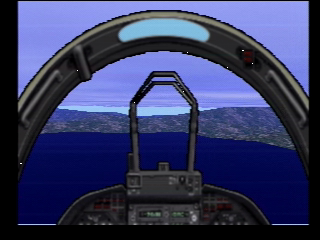
YouTube Video Link Since the purpose of this article is to demonstrate the theory behind the method instead of any particular implementation details for specific graphics API's, we will not go into how to do this on other platforms besides the PS2. In Direct3D and OpenGL it is probably best to stick to perspective projection since they will calculate the projection matrix for you and handle the texture coordinates as is.
But even without texturing, this technique can still be useful for creating an artificial horizon, such as on the instrument panel on airplanes, or for rendering the HUD of jet fighters. It is demonstrated in the viOrthographic.exe demo which uses an orthographic projection instead of a perspective projection since we do not need our perspective to be calculated by the API.
Adding Terrain
So great, we can now create a pretty nice looking horizon no matter where the camera is located or how it is oriented. However, so far we have only been able to render completely flat ground. What if we want to have some hills and mountains? Well, since we know what our footprint is on the two-dimensional ground plane, if we divide up the plane into a regular grid of equally sized rectangular "cells", then all we have to do is figure out which cells overlap our footprint polygon and draw those cells using a heightmap to create three dimensional triangles and thus our terrain.
So how do we figure out which cells are overlapping? Well, if we think of our cells as pixels on a two-dimensional drawing surface, and our footprint polygon as a graphics primitive, then we can see how the scan conversion algorithm can be used, since it is the most common way to render graphics primitives onto a drawing surface.
The idea is that we create scan lines that have the same size as our grid cells and we scan along the line from one edge of the polygon that intersects the scan line to the next edge that intersects the scan line. All grid cells on the same scan line that lie between the two edges will be found by the scan.
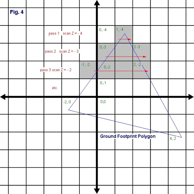 If we look at Fig. 4, we can see how this technique works. On the first scan we start at cells that have a z-coordinate of -4. We then scan from left to right and find that only one grid cell intersects, cell (1, -4). We then increment our scan line to z-coordinate -3, and scan again starting at edge A and going to edge B. This time we find grid cells (0,-3) to (2,-3). We continue the process until we have scanned all of the edges. You can see how this is done in the demo source in the files ScanConvert.h and ScanConverter.cpp. There are many books and resources that explain scan conversion, especially ones that deal with software rasterization where scan conversion is quite often used.
The one drawback to this technique is that as the camera gets higher and higher, the footprint gets very large and thus requires a lot of grid cells to cover it. Eventually, the frame rate will drop off by quite a bit. In the demo, this problem is alleviated by increasing the size of the grid cells as the camera goes up. So when it reaches 20 units in altitude, the cell size is doubled to 2000 units, and when it reaches 40, it is quadrupled to 4000, and so on. The heightmap tile size however remains the same so that the terrain does not get wider, it just gets courser with less detail.
The viTerrain.exe demo demonstrates this technique in action.
As you can see there is quite a lot of popping so this method of optimization is only useful for demonstration purposes but it does help to improve the performance of the demo so that we can really get a good idea of how the scan conversion works. If you really want to get the best performance when using this technique with terrain, you should certainly use one of the common terrain LOD techniques to render each grid cell, such as ROAM, geomorphing, geomipmapping, etc. That is left as an exercise for the reader.
Having the camera's world-space footprint can also be helpful when you do not need infinite terrain, but instead have a fixed set of geometry to represent your scenery. An example would be when you have several quadtrees to render terrain at different locations in world space. The camera footprint can be used in view-culling to determine if any of the geometry is visible from the camera. You simply need to perform 2D intersection tests between the footprint polygon and the geometry bounding boxes.
Conclusion
So there you have it, infinite scenery in both the horizontal and vertical dimensions with an extremely precise camera footprint that can be easily rendered in a very efficient manner.
Happy Coding,
Gabriel T. Delarosa
July 3, 2010
Bibliography:
Lamothe, Andre, "Tricks of the 3D Game Programming Gurus" (Sams Publishing, 2003, ISBN: 0-672-31835-0 )