Introduction
A scene graph is a very common structure used in computer graphics to organize the visible objects of a scene. By maintaining a hierarchy of objects in a scene, it becomes very intuitive to work with an object and its children. For example, if a vehicle object is added to a scene, whose children are its wheels, then by moving the vehicle we can automatically move the wheels as well. This automatic movement of the wheels is possible because the wheels are positioned relative to their parent, the vehicle. Relative positioning is a powerful concept, and is fundamental to the infinite scene graphs discussed in this article. Essentially, we must remember that whenever we position something in a 3D space, it is always positioned relative to something else, whether that something else is a vehicle, a planet, or a game universe.
Most scene graphs used in computer games today are restricted to being scene trees, as there will be a root scene node, and multiple generation of children underneath that, but never any cycles. For example, a common situation might be to have a city as the root node, with buildings and roads as its children. The children of the buildings will be the rooms, and the children of the rooms will be furniture. It is very uncommon in computer game scene graphs to see a scene graph node referencing itself or one of its parents, as it is more difficult to see any immediate application of how this would be useful. In our city, an example of a scene node referencing its parents is if, on the table inside a room in the city, there is a snow globe with a city inside of it, whose children are roads and buildings and etc...
Extending a scene tree to a scene graph allows us to create fractal-like objects with infinite details. In games, this means objects like trees or plants can be defined that have infinite detail. It allows the construction of unique worlds that would have otherwise been impossible to construct, such as worlds with the world contained in itself all over again. Some of the implementation details required for a true scene graph to be feasible will also be useful in their own right, allowing for massive scenes including objects of vastly differing magnitudes. Imagine zooming out from a leaf, to a tree, to a landscape, to a planet, to a solar system, and then to the entire galaxy, seamlessly.
This article will explain how to achieve an implementation of a true scene graph, as opposed to a scene tree. It will discuss how the scene graph idea itself, as well as the implementation details necessary to support it, can be applied to solve common and not so common problems in video games and other domains.
Defining the Scene Graph
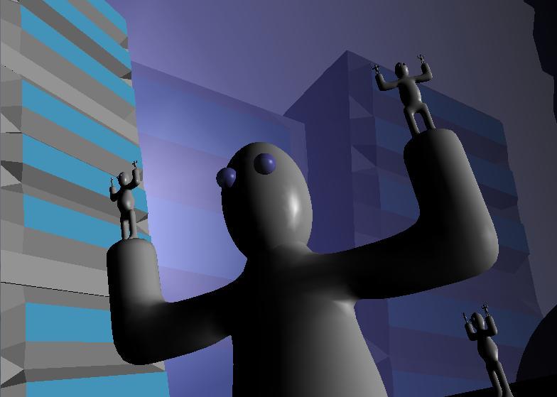
In order to begin discussing implementation details, we must first determine how to describe a scene graph. Imagine a man with his arms out, holding in each hand, another man with his arms out, holding in each hand, another man with his arms out, ad infinitum. If we were to explore a 3D scene like this, it might appear that there is an infinite amount of detail, so how can we hope to describe all of it? This is not quite true though. Just like how a recursive function is defined in a finite amount of code, we can also define this man scene in a finite amount of information.
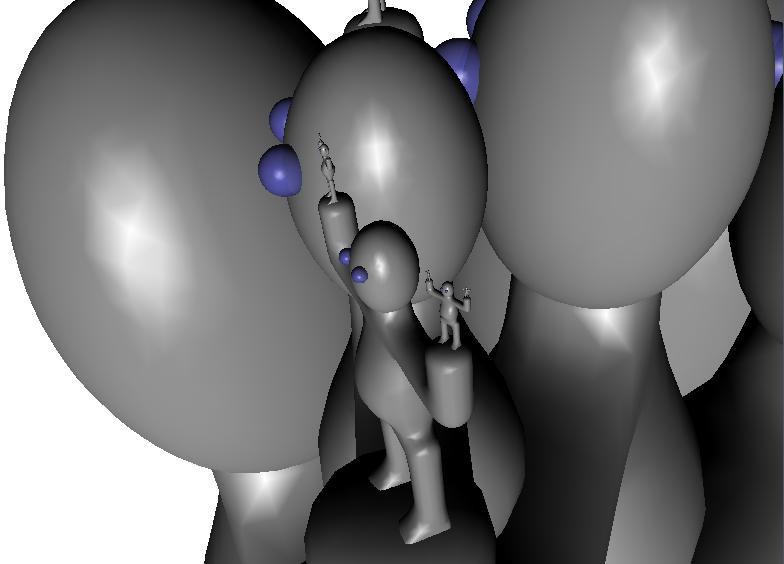
Figure 1: A scene graph where a node references itself
First, let's formalize the information in a few nodes of a standard scene tree. Imagine a scene consisting of a garage, with a car inside of that, and four wheels on the car. We might write this as follows:
Garage -> (GarageModel, M[sub]1[/sub]), (Car, M[sub]2[/sub])
Car -> (CarModel, M[sub]3[/sub]), (Wheel, M[sub]4[/sub]), (Wheel, M[sub]5[/sub]), (Wheel, M[sub]6[/sub]), (Wheel, M[sub]7[/sub])
Wheel -> (WheelModel, M[sub]8[/sub])
Where the line "X -> (Y[sub]1[/sub], M[sub]1[/sub]), (Y[sub]2[/sub], M[sub]2[/sub]), ..." reads: for all i, Y[sub]i[/sub] is a child of X, positioned relative to X by the linear transformation represented by the matrix M[sub]i[/sub]. In our example, Garage, Car and Wheel are the internal scene tree nodes, and GarageModel, CarModel and WheelModel are the leaf scene graph nodes, or terminal nodes. The terminal nodes have no children, and these are the nodes that actually result in a model being rendered when traversed during the scene graph pass.
In other words, drawing a garage involves drawing a GarageModel and a Car (which involves drawing a CarModel and four Wheels (which involves drawing a WheelModel)). Drawing any of the terminal nodes, in this example, implies rendering the model of the object (IE: a car mesh loaded in from 3D Studio Max).
Now, in order to allow for the definition of a true scene graph as opposed to a scene tree, we simply allow any of the Y[sub]i[/sub]'s in the line "X -> (Y[sub]1[/sub], M[sub]1[/sub]), (Y[sub]2[/sub], M[sub]2[/sub]), ..." to be X itself, or a parent of X. We discussed the example of a man holding himself above, and now we shall formally describe it:
Man -> (ManModel, I), (Man, M[sub]1[/sub]), (Man, M[sub]2[/sub])
Where I is the identity matrix, and M[sub]1[/sub] and M[sub]2[/sub] are linear transformations placing the unit cube in to the ManModel's hands. Figure 2 shows a graphical representation of the above, Man definition, as seen in the provided implementation tool.
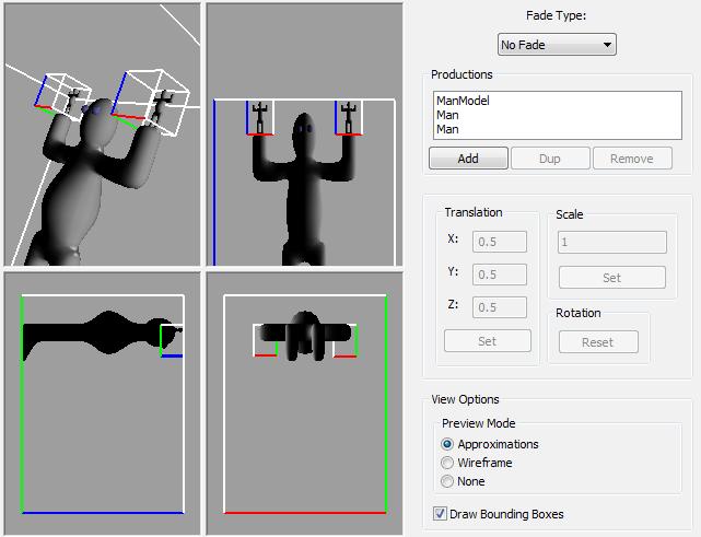
Figure 2: A graphical view of the "Man holding himself" scene definition. In the SceneComposer sample application
We now see that this seemingly complicated scene is actually very simply described.
Implementation Details
Now for the fun part. We will first discuss the difference between the Scene Graph definition, which is described in the section above, and the Scene Graph instance, which is a tree. We will then discuss how to terminate the recursion so that the loops introduced by a scene node referencing itself or its parent will not cause our rendering loop to go on forever. Finally, we will discuss how to maintain smooth transitions from very large objects, such as a galaxy, to very small objects, such as leaves on a tree.
Scene Definition vs. Scene Instance
Before moving on, we should discuss the difference between a scene graph definition, and a scene graph instance. While the definition of a scene graph is finite (for example, the "man holding himself" scene definition consists of only one line), the instance of a scene graph used for rendering will not be. The scene graph instance will always be a tree. The instance of a scene graph will be the tree formed by the following algorithm, whose input is the node in the scene definition to start instancing the scene at:
SceneInstanceNode CreateSceneGraphInstance(SceneDefinitionNode instanceStart): // Instance the current node SceneInstanceNode instancedNode = new SceneInstanceNode(instanceStart); // Instance the children of the current node ForEach child of instanceStart: instancedNode.AddChild( CreateSceneGraphInstance(GetSceneDefinitionNode(child)), GetMatrix(child)); return instancedNode; The application of this algorithm on the "Man holding himself" scene definition is shown graphically in figure 3. The transformation from a scene definition to a scene instance is important, because since the scene instance is a tree, we can now simply process (IE: render) it using standard "scene graph" processing techniques. Obviously, if the Scene Definition graph has loops in it, then the algorithm presented here will produce an infinite scene instance. The title of this article gets its name from the fact that the scene tree which results from the instancing process is dynamically constructed.

Figure 3: Example of CreateSceneGraphInstance algorithm applied to "Man holding man" scene
Instancing of the scene definition can be implicit or explicit. Explicit scene instantiation is described above, and involves formally processing the scene definition in to a scene instance, and then processing the resulting scene instance like a normal scene tree. Implicit scene instantiation would be to process the scene definition as it is traversed. That is, no "Scene Instance" data is explicitly created.
Explicit scene instancing can allow for a more powerful and robust system, since every instantiated scene node can now be treated as its own object. That is, if a person scene node happens to be instanced twice, each of these instances can now maintain their own, separate properties, such as animation and state, even though they originated from only one scene definition node. The downside to explicit instantiation though, is that it requires more memory.
Terminating the Scene Graph Instancing
As with all recursive algorithms, there must be a base case or else we will recurse forever. By restricting the linear transformations of the children of a node in the scene graph to be contractions (that is, the transformation has a component that scales the object down in size), we ensure that all of the children of a given node are smaller than that node. This implies that if we traverse down the nodes of a scene graph, we will arrive at smaller and smaller nodes. So, to terminate our scene instancing algorithm, we should stop recursing when our scene nodes are "small enough".
So when is a scene node "small enough" to stop recursing? A good method for determining this is to use the screen-space size of the node about to be rendered. This can easily be approximated by determining the maximum screen-space size of the bounding box for the given scene node. In order for us to calculate the screen-space size, we must have access to the model-perspective transform, and so this must be passed down our scene instancing algorithm. At each node, we should apply this transformation to that node's bounding-box, giving the screen-space points of the bounding-box. Since an axis-aligned bounding box is easier to deal with, we create a 2D axis aligned bounding rectangle enclosing the 8 screen-space points of the cube. Now it is simply a matter of determining the area of this axis aligned bounding rectangle (IE: width * height) to give an upper bound on the screen-space area of the node.
With the screen-space area of a scene node available to us, we can check whether it is below a rendering threshold or not. If the screen-space area of the scene node is too small, or below the threshold, then we return early, and this particular node, or any of its (possibly infinite) children do not end up in the scene instance tree. Since each recursion of the scene instancing algorithm takes us to smaller and smaller nodes, we are guaranteed to eventually arrive at nodes that are below the instancing threshold, guaranteeing that the algorithm will always terminate. What we are left with is only a part of the (possibly infinite) scene instance tree, but this is the part that is most relevant to us, since everything that was cut are scene nodes that occupy very little screen space.
Frustum culling can also be effectively applied at this stage to farther reduce the size of the resulting instance tree. This is easily done since we already calculate the screen-space bounding cube points of each node.
Infinite Zoom
The Zooming Problems
While enough has been explained already to produce a working true scene graph rendering system, it's usefulness is currently limited to allowing for objects whose level of detail is increased the closer you come to them (for example, a plant defined recursively will come in to more detail the more screen-space it occupies). While this is already a nice improvement to existing scene trees, we can make things a lot more interesting by allowing for the user to zoom infinitely closer to items in the scene.
Our first attempt might be to allow zooming by simply decreasing the camera's field of view. Since we are passing down the model-projection matrix to our scene instancing algorithm, the lowered field of view will be taken in to account and the level of detail will be adjusted accordingly. Unfortunately, it becomes very difficult to navigate around an object of focus we have zoomed in to because the slightest rotation of the camera will target a completely different space. Also, we run into floating point accuracy problems when zooming in too much.
Stepping back from the problem a bit (no pun intended), we realize that another way to achieve "zooming" is to simply move the camera closer to the object. Due to the mechanics of the the perspective projection matrix, this has the effect of making objects bigger (or smaller when you move away from them). Using this method allows us to maintain the same field of view, so camera rotations have the same degree of effect when "zoomed in". This method still leaves us with two problems though. The first problem is that if we continue to move our camera with the same speed we always had, it will now be moving much faster, relative to our new, smaller, object of focus. This is a problem because moving our camera 1 unit relative to a galaxy will move our camera an enormous number of units relative to a leaf, so clearly we must find a way to manipulate the speed of our camera. The second problem is that we still suffer from floating point accuracy problems, since floating point numbers do not allow us to represent an infinite amount of zoom to an object.
The Zooming Solution
The problem of floating point accuracy, and the problem of unsuitable camera speed when viewing smaller objects have a common solution. We simply need to realize that we can render the exact same scene under completely different coordinate systems, as long as everything is still positioned relative to each other. The observer of your world won't know if a leaf is 1 unit big or 100 units big, as long as it is still fifty times as small as the tree it is attached to. What we need to do is be able to dynamically select different scene nodes as being the scene's reference node, the node that every other node, as well as the current model-view transformation, is relative to.
An Alice in Wonderland game, for example, might start with the world being rendered with the frame of reference being a large scene containing a landscape with a rabbit hole in it, and all of the geometry consisting of the interior of the rabbit hole, with a desk at the bottom of it that has a little bottle with the words "DRINK ME" on it. Within this scene graph might also be a much tinier room with a tiny, locked door in front of it. This smaller room will have its own scene graph children in it as well. When Alice drinks the contents of the bottle, the game engine can then make the smaller room the new reference, everything else being made relative to it. As long as the new frame of reference is not scaled on an entirely different order of magnitude from the old frame of reference, the viewer will not notice when the reference frame switch is made, as the camera's position and orientation will also have changed to be relative to the new frame of reference.
By taking the transformation that positions an object relative to the current frame of reference (calculated by accumulating the matrices in the scene graph leading from the frame of reference to the object in question), and inverting it, we obtain a transformation that positions the current frame of reference relative to the object in question. The following pseudocode shows how to calculate the matrix used to change the frame of reference:
Matrix FindRelationMatrix(sourceNode, destNode): // Helper function for getting the list of all a node's ancestors // In the returned list, the original node will be the first item // and the root will be the last NodeList GetAncestorsList(node): ancestorList = []; curNode = node; while curNode: ancestorList.Append(curNode); curNode = curNode.parent; // Accumulate the tranform matrices leading from the source node to // the destination node Matrix sourceToRoot = Identity; Matrix rootToDest = Identity; For node in GetAncestorList(sourceNode): sourceToRoot = sourceToRoot * node.GetTransform().Inverse(); For node in GetAncestorList(destNode): rootToDest = node.GetTransform() * rootToDest; return rootToDest * sourceToRoot; By applying this transformation to the current model-view transformation, we obtain a new view transformation that is relative to the object we wish to re-focus on. If the new frame of reference is smaller than the old one, we have just made the entire universe bigger, but since the view matrix has been adjusted to account for this as well, the universe appears unchanged. Now, though, we can begin to show even smaller objects that would have been problematic due to floating point accuracy in the previous frame of reference. By continually changing the frame of reference, we can continue to zoom in (or out) of objects infinitely. Notice also that since the view matrix is continually being modified, then so is the velocity of the camera, so that when we switch to a smaller frame of reference, the camera automatically begins to move slower. This is desirable, since it means the camera will now move at a reasonable speed to allow the viewer to analyze the detail of a much smaller object.
Rendering Scenes With Big, Distant, Detailed Objects
When viewing a very small object up close, it is possible for the viewer to be also looking at a very large object in the background. Think of the camera looking at the tip of a leaf, while behind the leaf is a planet, and behind the planet is a sun. Even though the planet and sun are far away, they're also really big, so they still occupy considerable screen-space area. We can't render a leaf, a planet, and a sun in the same scene though, because the z-buffer would provide very poor quality for the distant objects, resulting in ugly z-fighting artifacts.
A solution to this problem exists by rendering the the scene instance tree in a breadth first fashion, starting at the root. This has the effect of drawing the largest objects first. A "rendering reference frame" is created, starting with the root (biggest) node. The camera is re-positioned relative to this reference frame, and rendering begins. When recursing down towards the current object of reference (IE: towards the viewer), we track how much the scale has changed from the root node. When it is detected that the scale has been reduced past a given threshold, we clear the current z-buffer, reset the "rendering reference frame" to the current scene node, adjust the camera according to the new reference frame, and continue rendering in to this new "layer".
The layering approach works because we are traversing the instance scene tree towards the camera, so every time we enter a child that also contains the camera, we are rendering objects closer to the viewer. A downfall to this solution is that there will be rendering order artifacts if the bounding boxes of two scene node children overlap. In this case, it would be possible to flag that the particular node is "required to be rendered with the same z-buffer as its children", so the z-buffer will never be cleared when jumping from that node to its children.
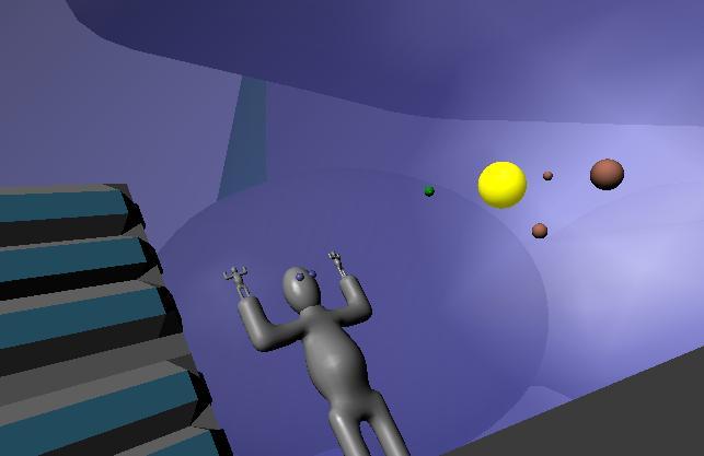
Figure 4: A man on in a city on a planet, with another solar system in his galaxy, all rendered in the same scene
Applications
To put what's been previously described in to some perspective, a description of how the system might be used in a game like Spore will be described. I do not know how Spore implemented their transitions from planet-side views to galactic views, I only discuss here how it might be implemented using the dynamic scene graph system.
In Spore, the player can obtain a spaceship with which they can zoom out to a view of the entire galaxy, flying around from one to the other. The player can fly to a solar system in a galaxy, and then a planet within the solar system. When the player flies towards a planet, the camera zooms in to the planet surface where the player can manage the local situation. This cannot be implemented relative to a single coordinate space, because the size of a planet surface is microscopic compared to the size of the galaxy, so there would be large floating point errors, resulting in inaccurate graphics and collisions on the planet surface.
We do not wish to generate the entire galaxy and every planet within it, since if we allow for an arbitrary amount of detail on all scales, we will run out of memory. Furthermore, in the context of a game with a changing game-state, it is less trivial to apply the dynamic scene graph generation strategy, because we want the game to never forget that we built a city on planet A, even if we're on the other side of the galaxy, and planet A is now too small to be in our scene graph instance. With these challenges overcome, we would have a reasonable framework to implement a Spore-like game within. We will discuss these topics now.
Galaxies of Arbitrary Size and Detail
In order to support galaxies of arbitrary size and detail, we need a method of only fetching the detail currently relevant to us, while ignoring the rest. Suppose the planets in the galaxy and everything on them are created procedurally. When we go to instance the solar system scene graph nodes, they should be defined in such a way that the instancer is instructed to randomly position children planet nodes. The planet nodes will then be instanced as required, where they should instruct the instancer to randomly generate a landscape and populate it with cities. The cities may themselves be child nodes which are instructed to procedurally generate buildings and streets, and so on. Since the creation processes only happened during instancing, and we only instance scene graph nodes that are visible to us, then we are able to construct only the part of the universe that we are currently concerned with.
This same technique can be extended to support artist-defined universes. In this case we can load in the art assets for the player's starting point and then, during scene graph instancing, for every node that contains an art asset, we determine its children and whether or not to instance them. If we decide it's relevant to instance an art asset's children, then we load those child assets off the disk and store them in memory. Art assets should be removed in a Least Recently Used fashion, so that memory for art that is no longer relevant is continually freed. Once again, this method can be used to achieve an artist-defined universe with arbitrary detail that is completely connected, yet automatically only the portions of that universe relevant to the player will be loaded in to memory. It should be noted here that in this case, the art assets are actually nodes of the scene definition, so the actual scene definition will also be dynamically extended as new assets are loaded. This technique may also be useful for applications like Google Earth.
In order to for these more sophisticated instancing methods to function properly, we cannot blindly re-instance all our objects from the scene definition. We must remember the objects we have instanced, and only re-instance objects that have just become relevant. This is discussed next.
Persisting Instanced Nodes
Before we proceed, it should be recognized that in a game like Spore, it would be convenient to deal with a planet and everything in it as a whole, as it is difficult to represent a spherical planet with mountains on it as a scene graph. What we can do instead is that when the planet is instanced, we can also instance the randomly generated terrain using standard terrain generation techniques as well as initialize a spatial partitioning structure to deal with cities and the critters moving around the planet. Everything instanced as part of the planet will operate within the planet's frame of reference, which is given meaning by the planet node's position within the scene graph instance.
When a planet is instanced, then, we would want to initialize many items inside of it. Furthermore, since the player can affect the state of an instanced planet, we would like to remember the changes they made to the planet's state. To accomplish this, we should mark the planet instance as "unforgettable" to the scene graph system when the player makes a change. In doing so, the planet should never be de-instanced, even if it is considered no longer relevant (at a given moment). In remembering a planet, we are forced to remember all of the planet's parents as well, otherwise the system has no way of recognizing where the planet fits in with the rest of the scene graph. This is not unreasonable on memory though, since the height of the instanced scene tree is logarithmic with respect to the amount of nodes in the tree.
It is true that a player could then create a "worst case" by jumping from planet to planet making slight changes, forcing our system to remember more changes than we have room for. This is an inevitable limitation however, as the computer is asked to literally remember more things than it has a memory for. A possible solution would be to assume that if the computer can't remember all the player's changes, then the player probably can't either, and we can apply a Least Recently Used scheme to forget changes that the user has made to the game world.
In order for instance remembering to work, our scene instancing algorithm should be augmented with logic to check that a scene element has already been instanced and if so, it should re-use the existing instance instead of re-instancing. Pseudocode is given for this style of instancing, where the algorithm will take the root of an existing scene instance tree and instance any nodes that have not yet been instanced, while deleting nodes that no longer need to exist.
CreateSceneGraphInstance(SceneInstanceNode instanceStart): // Check if this node's children have already been instanced if instanceStart.HasChildren(): if IsRelevant(instanceStart): // Simply recurse in to the children, in this case ForEach child of instanceStart: CreateSceneGraphInstance(child); else: // Children are no longer needed, get rid of them instanceStart.DeleteChildren(); else: // Children have not been instanced. If IsRelevant(instanceStart): // And they are relevant, so instance them instanceStart.InstanceChildren(); A sample implementation is provided. It includes two programs, Scene Composer and Scene Explorer. Scene Explorer can be used to quickly view a scene created by Scene Composer. Scene Composer allows you to import Wavefront Obj model files and then compose them together to create a scene graph definition. The sample scene composer allows you to specify more than one production with the same symbol on the left side (ie: "Planet -> RedPlanet" and "Planet -> Green Planet"). In this case, the scene instancer will randomly choose one of these productions when it instances a Planet symbol. Since it is randomly choosing a production to use here, we must remember the choice so that when we instance the next frame, we do not randomly choose another production. This is implemented by keeping the instance tree available for the next frame, at which time the instancer will traverse the old instance tree, instancing new symbols only when they have not already been instanced. Symbols that become irrelevant are destroyed.
Some example scenes are provided. The "Fern" example attempts to re-create the popular 2D fern fractal, in 3D. It uses a green cylinder as the only model, representing the fern's "stem". It then uses the fern symbol recursively to represent the fern's branches. The final scene resembles a plant with infinite detail which can be zoomed in to or out of. This example demonstrates how the infinite scene graph system can be used to create objects of infinite detail.
The "Odyssey" example features a galaxy of solar systems of planets of cities of buildings with men in them. The buildings in the city have random heights, accomplished by having the "building" production randomly choose between four building heights, when instanced. The men in the scene recursively feature galaxies in their eyes, so the viewer can zoom in or out as much as they want. This example shows how one can implement an explorable Spore-like universe (although the instanced scene nodes maintain very little state separate from the scene definition).
The sample application is packaged as a Windows installer, which includes the above examples and others. The installer will place a README file in your start menu explaining how to use the SceneExplorer and the SceneComposer.
The source code is also available as a separate download as a zip file. It is built using SCons and requires some Boost libraries. I have not tested it on any compiler besides MSVC 2005 and MSVC 2008.
Conclusion
The full system described here consists of the combination of a number of techniques which compliment each other. Each of these techniques provides for interesting applications in their own right. These techniques can be applied together, or by themselves to solve common problems that arise in video games, as well as enabling new creative game-play ideas.
With a scene graph that can contain loops, we allow objects to have an infinite amount of detail, where the amount of visible detail is determined by the screen-space area that the object occupies. Objects such as plants can be defined recursively, similar to how the famous fern fractal is defined. Applying this technique can give a plant that occupies very little detail (and therefore graphics processing time) when far away, but is continuously refined as the viewer comes closer. Applying this technique allows an artist to describe an object in as much detail is they wish, letting the run-time engine determine how much of that detail to display at any time. A fern-like object constructed with the system is shown in figure 5.
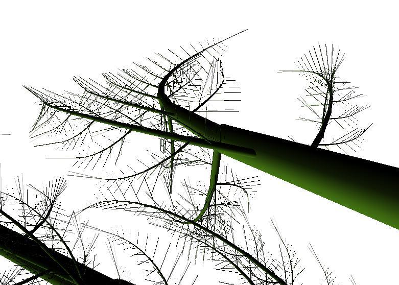
Figure 5: A view of a fern object. A green cylinder is the only model used
Using the system that allows for a change in frame of reference, we enable scene graphs where the very large objects, such as galaxies, can co-exist in the same data structure with the very small objects, such as leaves. This is a very powerful system, since a viewer can seamlessly move from a close up of the tip of a leaf, back to a wide-shot view of an entire galaxy. As long as the frame of reference is continually switched to a bigger (or smaller) one as the user zooms out (or in), one gigantic scene can describe an entire galaxy and everything inside it with intricate detail.
These techniques can also be applied to create previously unimaginable artistic continuous environments where the user can continuously zoom in to objects as far as they desire, cycling the user back to previous environments as needed. It opens the door to creative new ideas, and previously unimaginable scenes.
References
The model of the man was created in Blender by following the tutorial from this site