The computer graphics industry has seen dramatic leaps in visual fidelity due to advances in hardware, memory density, and display resolution in the past decade. Researchers in computer graphics have been exploring the dynamic range of the visual display and how to best make use of its limited display range for some time now. Rendering algorithms that utilize high dynamic range (HDR) imagery is one way to better utilize the display. With programmable graphics hardware widely deployed, game developers can take advantage of these effects in their game engines.
This white paper discusses the capture, storage and display of HDR images. The capability to display and process HDR imagery is widely available today - for example, in mainstream computer graphics chipsets such as the Intel(R) 965 Express Chipset and Mobile Intel(R) 965 Express Chipset family. The article also demonstrates the ability to use HDR images with the now available floating-point texture format support. This is demonstrated by environment mapping objects in a scene with HDR textures in real-time on integrated graphics processors.
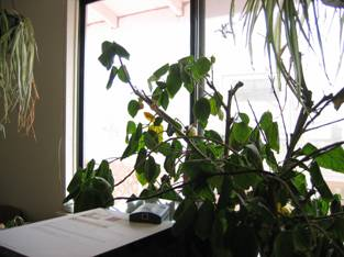
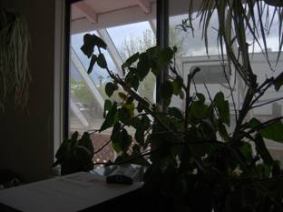
Figure 1-1. Tone Mapping with High Dynamic Range Images
The article first presents background on HDR imagery and describes the theory and the mathematics of HDR image capture and display with emphasis on Erik Reinhard's photographic tone reproduction operator. The authors then describe their own implementation of HDR environment mapping provided with this article including floating-point texture support on the Intel 965 Express Chipset and Mobile Intel 965 Express Chipset family, and a Pixel Shader 2.0 implementation of HDR tone mapping. An example of the results can be seen in Figure 1-1.
[size="5"]Background
[size="3"]A Trip Down the Image Acquisition Pipeline
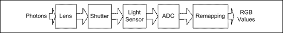
Figure 2-1. Image Rendering Pipeline
Figure 2-1 depicts the path photons take from the real world to be mapped into a RGB image.
Figure 2-1 depicts a simplified image acquisition pipeline inspired by [3]. After passing through the lens, photons travel through the shutter to a light sensor, typically a CCD. The shutter is used to control the amount of time the light sensor accumulates photons and the lens is used to focus the incoming photons onto the light sensor. After arriving at the light sensor, the photons are converted into digital values by passing through an analog digital converter (ADC). These digital values will travel through some final adjustments depending on the camera manufacturer and camera settings and be written to an image as RGB values.
[size="3"]Dynamic Range

Figure 2-2. Natural, Perceived, and Displayable Luminance Ranges
In Figure 2-2 we can see the variations in dynamic range of the human visual system compared to the dynamic range of visible light and LCD display range. The human visual system adapts the amount of incoming light via moderation of the pupil as well as chemical and neural processes in the photoreceptors and neurons. Photographic devices mimic this behavior via a lens aperture and exposure time.
However, in doing so, the remainder of the information outside the range of the lens and exposure combination is forever lost - a significant blow to the use of these images for real-time rendering purposes, where the conditions under which the light is perceived may warrant modification. In other words, we may want to capture all the information in of the full dynamic range in a scene, and only later chose which parts to discard. As we will demonstrate in this article, the use of HDR images allows for the storage of more lighting information in the source image, and therefore runtime modification of the end users perception of this lighting information.
[size="3"]Storage of HDR Images
After creating an HDR image, it will need to be stored for later retrieval, processing, and display. [20] has a summary of different formats for storing HDR images. Examples include Pixar's 33 bit log encoded TIFF, Radiance's 32-bit RGBE and XYZE, IEEE 96-bit TIFF and Portable FloatMap, LogLuv TIFF, and ILM's 48-bit OpenEXR format. Each format has its own set of advantages and disadvantages including file size, dynamic range, and quantization. For our work we have chosen to use the RGBE file format and half-precision floating-point textures to demonstrate HDR rendering with different data sources, including compressed formats. The RGBE format utilizes 32 bits per pixel, which we expand to 64 bits in our computations leaving the 16 bits of the alpha channel unused. Ultimately, the format you choose will be dependent on the context of your work and the tools available. We need a tool to manage and manipulate HDR images. Fortunately there is a tool available on-line to help in this effort, HDRShop. Since HDRShop exports RGBE files and RGBE files have an acceptable displayable range we chose to use them for our work [7]. Commercial software packages are also available, including Version 2.0 of HDRShop and Photogenics [13].
[size="5"]Theory
[size="3"]The Need for HDR Images
An image is composed of the response of each pixel of the sampling device. The light sensor has the largest error when near its maximum or minimum input. Since any value above the saturation point is mapped to the largest value for storage we have not obtained an accurate measurement of the amount of light hitting the pixel for a given exposure time. Therefore, in many cases images fail to accurately sample and store the intensities when HDR image techniques are not utilized. To compensate for the capabilities of today's digital cameras, it is useful to vary the exposure time and take a series of images. These images can then be used to gain a more accurate understanding of the light entering the lens and being sampled by the light sensor for later display as HDR images.
By storing a set of images with different exposure times it becomes easier to map the true luminance of a scene into the displayable range of whatever device or application limitations we have available. Much of the work in the film industry is motivated by the desire to have images that can be matched to the displayable range of film.
Uses of HDR images
HDR images are used for environment mapping of objects in a game engine. The motivation is to create a more accurate and compelling visual experience given the capabilities of today's hardware. In addition to HDR images being useful for environment mapping, they can also be used for motion blur and simulating characteristics of the human visual system when rendering. For example, it can be used in where the high luminance values are not clamped and used to demonstrate a depth of field effect [11], [8], [9].
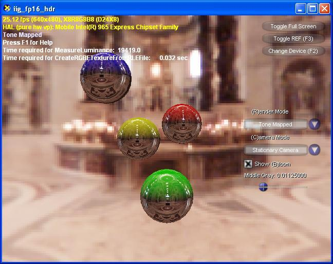
Figure 3-1. HDR Rendering Sample
[size="1"]St. Peter's Light Probe Image (C) 1999 Paul Debevec. Used with Permission.
Figure 3-1 taken from our High Dynamic Range Environment Map demo. We use DirectX* 9.0 Pixel Shader Version 2.0 on Mobile Intel 965 Express Chipset graphics with 16-bit floating point textures and an RGBE image to store and render the HDR environment maps.
[size="3"]Display
To this point we've covered the acquisition, usage, and storage of HDR images. Next, it is important to consider the display of HDR imagery. There has been research in creating displays that can more accurately render HDR imagery [19]. Use of the currently available graphics technology allows floating-point formats Therefore, it is necessary to find techniques that allow mapping the large variance in luminance stored in HDR textures into something that can be displayed.
Given the presence of floating-point texture support in current hardware, luminance values are preserved without the High Dynamic Range Texture Mapping, HDRTM technique discussed in [2]. This eliminates the need to decode and encode 8-bit color values utilizing the Alpha channel as a temporary store for the RGBE luminance exponent and allows us to use the 16-bit per RGB and Alpha channel format leaving the Alpha channel unused.
Due to the real-time requirements and the wide availability of programmable graphics hardware, the authors have chosen to implement a tone-mapping technique presented in [17] for the demo seen in Figure 3-1. For tone mapping, the idea is to map the HDR of the real world luminance to the lower dynamic range of the display device. In fact, since pixels are always constrained to some maximum value in the frame buffer, we always have performed tone mapping by applying a clamp operator per pixel that causes our display to act as a low pass filter, thus we lost much of the higher luminance of the scene. We would like to take a smarter approach. Ansel Adams faced a similar problem in photography. We choose to adopt a technique inspired by his work called the Zone System. The Zone System is still widely used in analog image acquisition today.
As seen in Figure 3-2, a zone is a range of luminance values, taking into account the reflectance of the print. There are eleven print zones ranging from pure black to pure white, each doubling in intensity. Each zone is represented with a roman numeral, Zone 0* through Zone X. The middle-grey value is the subjective middle brightness region of the scene, which is mapped to print Zone V in most cases. A photographer would take luminance readings of what was middle grey in a scene, typically this middle grey would be what would produce an 18% reflectance on the print. If the scene were low key this value would be lower in the spectrum of print zones. Similarly, if it were high key the middle grey would be one of the higher print zones.

Figure 3-2. Zone System Luminance Intensity Scale
Note: '0' was not a Roman numeral. In fact, the Romans had not yet discovered 0.
[size="3"]Mathematics of Reinhard's Photographic Tone Reproduction Operator
The first step in applying Reinhard's tone reproduction operator is to obtain an average luminance value, which we will use as the key of the scene. Normally, a simple average is fine, however since luminance values are an exponential curve we will use the logarithmic average luminance value, or log-average luminance as an approximation for the scene key. To compute this value, we first compute the luminance from our RGB values as follows:

Equation 1
Equation 1 uses the luminance conversion found in [1], which is based on modern CRT and HDTV phosphors.
Next, we compute the log average luminance using this value, summing over the entire image:

Equation 2
 is a small value to avoid taking the log of a completely black pixel whose luminance is zero. Now that we have the image key we would like to re-map the pixels into a new image that scales the values so we can give greater dynamic resolution to the upper range of luminance values. Since we know that .18 is the middle (zone V) in our logarithmic scale from 0-1 in intensity values, we use the ratio:
Equation 3

Equation 4
Equation 5
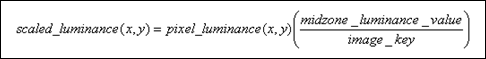
We still have two problems. First, most images have a normal dynamic range for most of the image and only a small percentage of the pixels have very HDR, for example at the light source such as the sun or a window. Equation 5 assumes a linear mapping, what we really want to do is a non-linear mapping to emphasize these areas of HDR. Second, Equation 5 can still produce values that lie outside of the 0.0 - 1.0 viewable on the monitor. This leads us to a final adjustment to our scaled luminance value:

Equation 6

Figure 3-3. Tone Mapped Luminance Scale
The image from Figure 3-2 modified by tone mapping. Notice now that all tones from 0 to X are in visible in the image and within the displayable range of 255 intensity values.

Figure 3-4. Tone Mapping Effects on Luminance
Luminance values before and after tone mapping algorithms in Equations 1-6 are applied. Code for this example is in Appendix A. For image_key we chose the value of 0.36.
For current real-time applications expressions 2, 5, and 6 are adequate and will bring all luminance values within a displayable range. Sometimes this is not always desirable and we would instead like them to burn out for certain values in the highest range of luminance. This is accomplished with a different tone mapping operator:

Equation 7
White_luminance refers to the smallest luminance value that will be mapped to pure white. Notice if white_luminance is large the fraction in the numerator of Equation 7 goes to 0 and we are left with Equation 6. However, if white_luminance is small we get larger values in the numerator of our expression, acting to enhance lower dynamic range pixels. In our examples, we use Equation 6.
[size="3"]Mapping Luminance to RGB
Next, to get the final RGB values we multiply the final luminance by each original RGB value respectively to compute the new pixel RGB values.
[size="3"]Conversion
The process to acquire a HDR image is relatively simple given the tools available today. A HDR image is constructed by collecting a set of conventional photographs with identical position and orientation and varying the exposure times, usually by varying the f-stop for each image. One way to create a HDR image is to implement the algorithm presented in [3] that can be used to recover the response function of the camera and use this information to construct a HDR image. This image will have pixels whose values represent the true radiance values in the scene. Another option is to use HDRShop, a tool that allows the manipulation of a set of low resolution images taken from a standard camera to be used to create a single HDR image [7].
For many applications of HDR images in entertainment where the incoming radiance at a point is important, a light probe is a more suitable format. A light probe is created by placing a mirrored ball in the environment and taking pictures from both sides. The result is an environment map: a set of ray samples (an image) of all the rays of light intersecting the point at the center of the light probe from each point in space. This can then be rendered into a high resolution sphere map or cube map for use in the rendering pipeline and is used to approximate the light rays intersecting the object we are environment mapping.
[size="5"]Implementation
[size="3"]Demo
Included with this article is an implementation of HDR file loading into half-precision floating point textures and image key calculations utilizing the HDRFormats demo from the Microsoft DirectX* SDK [10]. The demo also allows interactive adjustment of the midzone_luminance (referred to as MIDDLE_GREY in the demo) from Equation 5 to allow the reader to better understand how adjustments to the midzone luminance value affect the resulting image. Additionally, we noticed that a pure implementation of the mathematics of tone mapping for each image could result in images that changed tone too dramatically from frame to frame. Therefore, we limit the amount the image_key can vary from frame to frame to prevent the image from changing too drastically, allowing the image to 'settle' to the correct value after a few iterations. The result was much more aesthetically pleasing, and is a more accurate depiction of what the light does in situations where the light does vary dramatically.
[size="3"]RGBE Format
The RGBE format is suitable for storage of high dynamic imagery for real-time graphics and was used for our implementation. RGBE was originally created by Greg Ward for his Radiance software package [15]. The format consists of an 8-bit mantissa for each Red, Green, and Blue channel along with an 8-bit exponent for 32 bits per pixel as seen in Figure 4-1. They share the exponent thus reducing the storage required significantly when comparing to a 32 bit per channel format. (32 bits per float * 3 = 92 bits per pixel vs. 32 bits per pixel). A downside is a lack of dynamic resolution between color channels since you are sharing the exponent for all of the color channels.

Figure 4-1. 32-Bit RGBE Format
Figure 4-1 depicts the 8 bytes per channel for Red, Green, Blue and a shared exponent value that is used to represent the HDR images in our examples. The shared exponent is in the channel typically reserved for the alpha channel in an image.
Encoding and decoding using the RGBE format is easy as the method RGBE_ReadPixels_RLE(...) found in [21] returns 3 RGB floating-point values automatically adjusted for the shared exponent.
[size="3"]High Dynamic Range Image Key Calculation
To avoid having to transfer the image over the bus to compute an image key we calculate this on the CPU using an image_key calculation included in the example based on [17]'s luminance tone reproduction operator. Deciding whether to calculate the image key on the CPU or the GPU is application, graphics card, and graphics bus dependent.
[size="3"]Pixel Shader for Integrated Graphics
We have also written a pixel shader in HLSL that supports using HDR images for environment mapping on Intel 965 Express Chipset and Mobile Intel 965 Express Chipset family Integrated Graphics. This chipset family is optimized for DirectX 9.0c support and uses DirectX's Intel-architecture-optimized Platform Specific Graphics Processing (PSGP) Vertex Shader 3.0 and Pixel Shader 2.0. The tone mapping described earlier in the pixel shader translates RGBE images into floating-point textures. The complete shader source code is provided in the effects file in the demo.
[size="3"]HDR Samples in the Microsoft DirectX 9.0 SDK
Microsoft has provided examples in the DirectX SDK that demonstrate some of the above techniques [10]. They provide examples that show HDR in several different scenarios. HDRCubemap is a demonstration of HDR lighting and cubic environment mapping that uses floating-point cube textures to store values where the total amount of light illuminating a surface is greater than 1.0. HDRFormats shows a technique for displaying HDR images on hardware that is not capable of using floating-point textures. The most notable difference apart from our usage of floating-point texture support, is that this sample is not tied to the DDS file format, therefore any HDR image that is encoded by HDRShop can be used. HDRLighting demonstrates blue shift under low light and bloom under intense lighting conditions as well as under and overexposing the camera.
[size="5"]Future Work
The authors are considering areas for future work. We would like to experiment with per-pixel tone mapping. [17] discusses a technique to simulate the photographer's use of dodge and burn. Dodge and burn is the action of adding or subtracting light from areas in the print to increase or limit exposure, usually done with a piece of article with a hole cut out or a small wand. Think of it as choosing a key value for every pixel. Since we wanted a fast tone mapping technique we chose not to focus on this operator, but as graphics hardware becomes faster per pixel tone mapping operators will surely be able to be done in real-time. Another alternative to consider is the application of a tone mapping in regions of luminance values by determining local keys to apply either the per pixel tone mapping or the average luminance value operator we described in detail above.
[size="3"]References
[1] [Akenine-Moller02] Tomas Akenine-Moller and Erik Haines. Real-Time Rendering, 2nd Edition. Page 193. AK Peters. 2002.
[2] [Cohen01] Jonathan Cohen, Chris Tchou, Tim Hawkins, and Paul Debevec. Real-Time High Dynamic Range Texture Mapping. In Rendering Techniques 2001. S. J. Gortler and K. Myszkowski, eds. 313-320.
[3] [Debevec97] Paul Debevec, Jitendra Malik. Recovering High Dynamic Range Radiance Maps from Photographs. SIGGRAPH 1997. 1997. Pages 369-378.
[4] [Debevec02] Paul Debevec. Image-Based Lighting. Computer Graphics and Applications. March/April 2002. Pages 26-34.
[5] [Ferwerda96] James A. Ferwerda, Sumanta N. Pattanaik, Peter Shirley, and Don Greenberg. A Model of Visual Adaptation for Realistic Image Synthesis. SIGGRAPH 1996. Pages 249-258.
[6] [Halsted93] Charles Halsted. Brightness, Luminance, and Confusion. Information Display. 1993. http://www.crompton....ight/lumin.html.
[7] [HDRShop04] Software for creating, editing, and saving HDR imagery. http://www.ict.usc.e...aphics/HDRShop/. 10/29/2004.
[8] {Kawase03] Kawase, Masaki. Framebuffer Post-Processing Effects in DOUBLE S.T.E.A.L. (Wreckless). Presentation. Game Developers Conference 2003.
[9] [Kawase04] Kawase, Masaki. Practical Implementation of High Dynamic Range Rendering. Presentation. Game Developers Conference 2004.
[10] [MSSDK04] Microsoft Corporation DirectX 9.0 SDK Summer 2004 Update. http://www.microsoft...en&categoryid=2. August 2004.
[11] [Northrop04] Northrop, Cody. High Dynamic Range Lighting Brown Bag Presentation. Intel Brown Bag Lunch. 5/26/2004.
[12] [OpenEXR04] The OpenEXR web site: http://www.openexr.org/downloads.html. August 19, 2004.
[13] [Photogenics04] http://www.idruna.com/downloads.html.
[14] [Probe04] Light Probe Image Gallery. http://athens.ict.usc.edu/Probes/. 9/8/2004.
[15] [Radiance04] http://radsite.lbl.g...iance/HOME.html. Radiance Imaging System. August 2004.
[16] [Reinhard04] Erik Reinhard, Personal Email Communication. July 30, 2004.
[17] [Reinhard02] Erik Reinhard, Michael Stark, Peter Shirley, and James Ferwerda. Photographic Tone Reproduction for Digital Images. SIGGRAPH 2002. Pages 267-276.
[18] [Shastry99] Anirudh S. Shastry. High Dynamic Range Rendering. http://www.gamedev.n...e/hdrrendering/.
[19] [Seetzen04] Seetzen, Helge, Wolfgang Heidrich, Wolfgang Stuerzlinger, Greg Ward, et. Al. High Dynamic Range Display Systems. 2004 ACM Transactions on Graphics, Volume 23 Number 3. SIGGRAPH 2004. Pages 760-768.
[20] [Ward03] Greg Ward. Global Illumination and HDRI Formats. SIGGRAPH 2003 Course #19: HDRI and Image Based Lighting. SIGGRAPH 2003.
[21] [Walter04] Bruce Walter. RGBE File Format. http://www.graphics.cornell.edu/~bjw/rgbe.html. 2004.
[size="5"]Appendix A: Simple Tone Mapping Implementation
//no warranties, expressed or implied, free for re-use

#include "stdafx.h"

#include "math.h"


#define N 11

#define delta 1.0f

#define MIDDLE_GRAY 0.36f

#define MAX_RGB 2048.0f

#define MAX_LUMINANCE ((0.2125f*MAX_RGB)+(0.7154*MAX_RGB)+(0.0721f*MAX_RGB))


// assume we have converted from RGB to luminance as described in the paper

float L[] ={  0.0f, 1.0f, 3.0f, 7.0f, 15.0f, 31.0f, 63.0f, 127.0f, 255.0f,

511.0f, 1023.0f, 2047.0f};


/* L refers to Luminance, wanted to fit on a page */

float L_NormalizedFloats[N];

float scaled_L[N];

float final_L[N];

int final_pixel_vals[N];


void _tmain(int argc, _TCHAR* argv[])

{

  float sum = 0.0f;

  float log_avg_L = 0.0f;

  float a = MIDDLE_GRAY;


  for(int i=0;i
  {

    float max = 0.0f;

    max = (float)MAX_LUMINANCE;

    L_NormalizedFloats = L/max;

  }


  for(int i=0;i
  {

    sum += (float)log((double)(L_NormalizedFloats+1.0f));

  }


  log_avg_L = (1.0f/((float)N));

  log_avg_L *= exp(sum);

  float weight = 0.0f;

  weight = a/log_avg_L;


  for(i=0;i
  {

    scaled_L = (weight*L);

  }


  for(i=0;i
  {

    final_L = scaled_L/(1.0f+scaled_L);

    int intL = (int)(final_L*255.0f);

    printf("[%d] = %f %d\n",i,final_L*255.0f, intL);

  }


}

