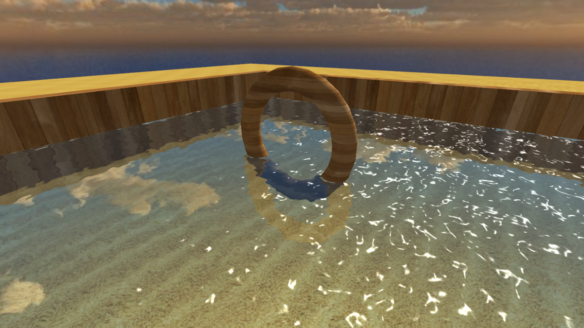
In most modern games, colour rendering is definitely the best way to portray the richness of the 3D graphics and lighting effects achievable on current hardware. However, as games such as L.A. Noire have successfully demonstrated, playing a game in old-style black and white graphics can completely transform the way in which the player percieves the same scene. This small article will show one way (of many!) to render your 3D geometry using a greyscale pallette rather than in full colour, using HLSL and DirectX. The following image shows a scene rendered in full colour:
...and this image shows the same scene, but this time rendered using the greyscale colour conversion explained in this article:
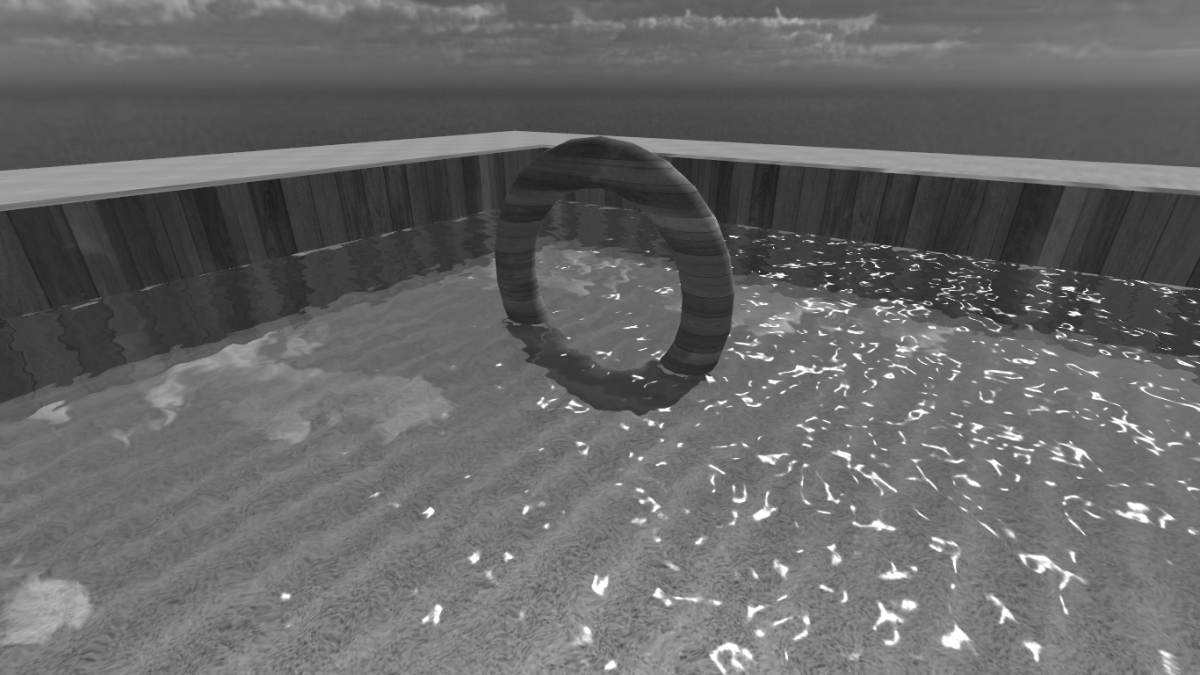
Neither of these images have been converted or tweaked in an external graphics program - they are rendered purely using Direct3D.
The concept
If you've experimented with even basic 3D programming, you will know that a pixel typically contains four channels of information: R (red), G (green), B (blue) and A (alpha). Of course, the exact nature of the information held by each pixel on a render surface depends on the format you choose, but RGB will almost always be a part of it. You may also know that the colour value of each channel typically ranges from 0 to 255. Combinations of the numbers assigned to each colour channel will produce a mixture of the overall colour specified for each pixel. Here are some examples (given in the [R,G,B] format - we will disregard the alpha channel because it codes for transparency, not raw colour):
[255,0,0] [0,200,200] [200,255,0] [100,100,100] You may notice that the last colour, [100,100,100], is a shade of grey. You may also notice that all of the colour channel values are the same, that is, each one carries a value of 100 for R, G and B. This is the key to achieving a greyscale effect - in order to avoid rendering in true colour, all of the colours must carry a similar weight, meaning that none will dominate over the others, and the result will be a shade of grey ranging from total blackness (given as [0,0,0]) to pure white (given as [255,255,255]). Achieving this effect is relatively simple, especially if you already have a shader to render in true colour.
Converting from colour to greyscale
It is a simple matter to create a greyscale effect given colour information for each pixel. Let's say we have calculated a colour of [0,100,200] for a given pixel, again in the [R,G,B] format, excluding alpha. To ensure that each colour channel has the same value while also choosing a greyscale shade which is representative of the brightness of the original colour, there are two steps to take, all of which can easily be achieved in a HLSL pixel shader:
- Take an average of the R, G and B channels for the pixel
- Assign a new colour to the pixel by entering this calculated average into each colour channel while preserving the original alpha value
That's all there is to it! If we wanted to calculate the greyscale equivalent of our [0,100,200] pixel, we would arrive at an average of 100 (because (0 + 100 + 200) / 3 = 100), and so our final pixel colour would be [100,100,100].
Putting it into a shader
Let's consider the following effect file designed to simulate diffuse and ambient lighting in black and white:
//Greyscale rendering shader, created by George Kristiansen

////////////////////
//Global variables//
////////////////////

float4x4 World;
float4x4 WorldViewProjection;
float LightPower;
float LightAmbient;
float3 LightDir;
Texture xTexture;

//////////////////
//Sampler states//
//////////////////
sampler TextureSampler = sampler_state
{
    texture = ;
    magfilter = LINEAR;
    minfilter = LINEAR;
    mipfilter = LINEAR;
    AddressU = Wrap;
    AddressV = Wrap;
};

//////////////////
//I/O structures//
//////////////////

struct PixelColourOut { float4 Colour : COLOR0; };
struct SceneVertexToPixel {
    float4 Position : POSITION;
    float2 TexCoords : TEXCOORD0;
    float3 Normal : TEXCOORD1;
    float4 Position3D : TEXCOORD2;
};

///////////////////////////////////////////////////////////////////////
//TECHNIQUE 1: Shaders for drawing an object using greyscale lighting//
///////////////////////////////////////////////////////////////////////

SceneVertexToPixel GreyscaleVertexShader(float4 inPos : POSITION, float2 inTexCoords : TEXCOORD0, float3 inNormal : NORMAL)
{
    SceneVertexToPixel Output = (SceneVertexToPixel)0;
    Output.Position = mul(inPos, WorldViewProjection);
    Output.Normal = normalize(mul(inNormal, (float3x3)World));
    Output.Position3D = mul(inPos, World);
    Output.TexCoords = inTexCoords; return Output;
}

PixelColourOut GreyscalePixelShader(SceneVertexToPixel PSIn)
{
    PixelColourOut Output = (PixelColourOut)0;
    float4 baseColour = tex2D(TextureSampler, PSIn.TexCoords);
    float diffuseLightingFactor = saturate(dot(-normalize(LightDir), PSIn.Normal))*LightPower; float4 trueColour = baseColour*(diffuseLightingFactor + LightAmbient);
    float greyscaleAverage = (trueColour.r + trueColour.g + trueColour.b)/3.0f;
    Output.Colour = float4(greyscaleAverage, greyscaleAverage, greyscaleAverage, trueColour.a);
    return Output;
}

technique GreyscaleObject
{
    pass pass0 {
        VertexShader = compile vs_2_0 GreyscaleVertexShader();
        PixelShader = compile ps_2_0 GreyscalePixelShader();
    }
}
As you can see, the vertex shader simply deals with transformations and matrix-based calculations. These are not dependent on whether the scene is drawn in greyscale or colour. The pixel shader comprises of lighting calculations which are present in pretty much every 'general' lighting shader. The texture applied to the object being drawn is sampled, a diffuse lighting contribution is calculated based on the normal and light direction, and the colour of the pixel (trueColour in the pixel shader) is found based on diffuse and ambient light. However, the final colour of the pixel is calculated using the averaging method desribed above to create a shade of grey where each colour channel has the same value. This ensures that any geometry drawn with the shader appears in greyscale rather than true colour.
Conclusion
This is one of many methods for drawing in greyscale. It is also possible to render the entire scene to a texture in colour, and present the scene after applying a similar calculation to this offscreen render target. This ensures that the entire scene is simultaneously converted to black and white post-render, rather than individual objects in realtime. There are also other formulae and calculation methods for doing the conversion, but this is possibly the simplest method, and it produces very respectable results.
Top image is a raw capture from SimCity set to Film Noir graphics filter


Great article!
I'm wondering if the color to grayscale conversion could be improved by calculating the luminance of each pixel instead of using a simple average. The human eye perceives red, green and blue differently, so each color component should be weighted when calculating a luminance value because each component contributed to its perceived brightness by a different amount. I think this would improve the contrast of the grayscale renderings.
A quick google search yielded the wikipedia article with the formula used by HDTVs:
Luminance = 0.2126*R + 0.7152*G + 0.0722*B
Which makes sense because blue would contribute the least to the perceived brighness of a pixel, while green would contribute the most as the human eye is best at seeing the color green.