Introduction
For many a hobbyist developer, the XNA Framework has been a gift from above. The combination of a robust game-development framework with MicrosoftAEs venerable Direct3D graphics back-end can be a winning combination for student programmers making their first game, or bedroom coders who donAEt have time to waste on creating tedious boilerplate code. With all of the framework classes and samples dedicated to showing you how easy it is to get a very simple game up and running in 30 minutes, itAEs pretty easy to forget that with XNA itAEs possible to craft complex, professional-level games by making the most of features like the Content Pipeline (even without a professional budget!). In that regard, this article is going to walk you through an implementation a 3D content authoring system that can allow you to seamlessly integrate XSI ModTool with your gaming engine.
Prerequisites
This article assumes at least basic familiarity with: C#, the XNA Framework graphics classes, the XNA Framework Content Pipeline, and HLSL. To compile the sample code, you will need to have XNA Game Studio 2.0 installed as well as Visual Studio 2005 (Visual C# Express 2005 can be used). The sample project also references the XSI Crosswalk Importer assembly, which is installed to the ModTool installation directory. Make sure this reference is properly set before compiling (the section titled ?Publishing The Model And Importing It Into The Content Pipeline? details this process).
Why Bother With Content Authoring Integration?
If you scan through the rest of the article and see the amount of work involved, you may be wondering ?why should I even bother with this?? Or you may be thinking ?this seems like overkill for my small project.? After all the XNA Framework is rather flexible, and itAEs perfectly feasible to find other ways to get content into your game that doesnAEt just use BasicEffect. For example, the ShipGame starter pack uses a custom NormalMapping effect for all meshes. And it does it in a very simple way: by simply ignoring the effect assigned to the mesh being rendered and using the NormalMapping effect instead. This of course works, but has limitations: What if you donAEt want to use just one effect for everything? What about effect parameters that arenAEt texture-based? Should the artists be messing around with the code to get what they want?
Content authoring integration does not have these disadvantages. Instead it has the following advantages:
- Artists can handle creation and importing of models without programmers getting involved
- Artists can get a real-time preview of the model in the modeling application, allowing them to get what they want quicker
- Every aspect of a modelAEs appearance is defined in the modeling tool, and completely contained in the model fileAEs data. If a consistent material parameter interface is used as well, this allows you to greatly simplify your rendering code as it wonAEt need to handle any special cases ? all models are treated the same (this is a benefit even if youAEre a one-man-band: simple code is always better).
Why XSI ModTool?
When it comes to 3D modeling, 3D Studio Max and Maya are usually the first names to come up. TheyAEre fantastic, full-featured applications and itAEs much more likely that a 3D artist is going to be familiar with one of them. However they pose a huge problem for any hobbyist developer: they cost money ? a lot of money. ModTool, on the other hand, is completely free for non-commercial use. While there are other free tools available (such as Blender), ModTool is conveniently designed to be integrated with XNA Game Studio project. Plus, it supports the ability to use real-time previewing of Direct3D effects with models, which is crucial for our content integration system.
Implementation
An Effect-Based Material System
3D models have two important attributes weAEre concerned with: geometry and materials. The geometry will determine the shape of the model, while the materials will determine what the surface of that geometry actually looks like. For our content authoring pipeline, weAEre going to use Effects as primary building blocks for materials. Each material effect will determine the basic type of material weAEre working with: some examples can include a basic texture-mapped surface, a normal-mapped surface, a reflective surface that uses an environment map, a surface with a fur shader, a metallic surface, a cel-shaded surface... whatever it is the actual game calls for.
Each material effect will have a set of artist-editable parameters, which can be tweaked in ModTool (in real-time) in order to further customize an effect. In the actual effect these parameters are implemented as textures or as shader constants.
A Consistent Effect Interface
One of the goals we laid out earlier was that we wanted our material effects to be interchangeable as far as our rendering code is concerned. This means we donAEt want to have to treat any of our materials any differently: the code should be able to just set the shader constants it needs to set the same way for every effect. To facilitate this, weAEre going to create a file containing the shader constants common to every effect and #include it in every material. WeAEll call this file ?mat_Common.fxh?, and it looks like this:
float4x4 g_matWorld; float4x4 g_matWorldInverse; float4x4 g_matView; float4x4 g_matProj; float3 g_vCameraPositionWS; float3 g_vLightAmbient; float3 g_vLightDirectionWS; float3 g_vDirectionalLightColor; We have a few basic constants here: transform matrices used to transform vertices to the various coordinate spaces, the camera position in world-space, and ambient lighting color, the direction of a directional light in world-space, and the color of the directional light. For now weAEll keep things simple and leave it at one directional light.
A Normal-Mapping Shader
As our first material type, weAEre going to implement a basic normal-mapping shader. If youAEre not familiar with normal-mapping, it works by sampling a per-pixel normal value from a texture and using that value for lighting calculations. This allows an otherwise flat surface to have the appearance of having much more geometry. These normal values we sample from the texture are in tangent-space, which means in the vertex shader we transform the light direction and the view direction to tangent-space so that we can perform the lighting calculations.
Before we write our vertex shader and pixel shader, letAEs set up some parameters and textures. For parameters weAEre going to need a specular color and power (glossiness), and for textures weAEre going to need a diffuse map and a texture map.
float3 g_vSpecularAlbedo; float g_fSpecularPower; texture2D DiffuseMap; sampler2D DiffuseSampler = sampler_state { Texture = ; MinFilter = anisotropic; MagFilter = linear; MipFilter = linear; MaxAnisotropy = 16; }; texture2D NormalMap; sampler2D NormalSampler = sampler_state { Texture = ; MinFilter = anisotropic; MagFilter = linear; MipFilter = linear; MaxAnisotropy = 16; }; For our vertex shader, we first need to set up our vertex inputs. Models that are exported from XSI ModTool have a particular vertex format, which actually encodes the binormal and tangent in order to save space. The inputs for our vertex shader look like this: in float4 in_vPositionOS : POSITION0, in float3 in_vNormalOS : NORMAL0, in float4 in_vColor0 : COLOR0, in float4 in_vColor1 : COLOR1, in float2 in_vTexCoord : TEXCOORD0, in float4 in_vTexCoord1 : TEXCOORD1, in float4 in_vTexCoord2 : TEXCOORD2, in float4 in_vTexCoord3 : TEXCOORD3, in float4 in_vTexCoord4 : TEXCOORD4, in float4 in_vTexCoord5 : TEXCOORD5, in float4 in_vTexCoord6 : TEXCOORD6, in float4 in_vTexCoord7 : TEXCOORD7 Now like I mentioned, we need to do some unpacking of our binormal and tangent. The code for that looks like this: // Calculate the tangent and binormal float3 vTangentOS = (in_vColor0 * 2) - 1; float fSign = (in_vColor0.a * 2) - 1; fSign = (fSign > 0) ? 1 : -1; float3 vBinormalOS = in_vNormalOS.yzx * vTangentOS.zxy; Okay now wereAE all set up and ready to code our shaders. HereAEs the final mat_NormalMapping.fx file: float3 g_vSpecularAlbedo; float g_fSpecularPower; texture2D DiffuseMap; sampler2D DiffuseSampler = sampler_state { Texture = ; MinFilter = anisotropic; MagFilter = linear; MipFilter = linear; MaxAnisotropy = 16; }; texture2D NormalMap; sampler2D NormalSampler = sampler_state { Texture = ; MinFilter = anisotropic; MagFilter = linear; MipFilter = linear; MaxAnisotropy = 16; }; void NormalMappingVS( in float4 in_vPositionOS : POSITION0, in float3 in_vNormalOS : NORMAL0, in float4 in_vColor0 : COLOR0, in float4 in_vColor1 : COLOR1, in float2 in_vTexCoord : TEXCOORD0, in float4 in_vTexCoord1 : TEXCOORD1, in float4 in_vTexCoord2 : TEXCOORD2, in float4 in_vTexCoord3 : TEXCOORD3, in float4 in_vTexCoord4 : TEXCOORD4, in float4 in_vTexCoord5 : TEXCOORD5, in float4 in_vTexCoord6 : TEXCOORD6, in float4 in_vTexCoord7 : TEXCOORD7, out float4 out_vPositionCS : POSITION0, out float2 out_vTexCoord : TEXCOORD0, out float3 out_vLightDirTS : TEXCOORD1, out float3 out_vViewDirTS : TEXCOORD2, out float3 out_vPositionWS : TEXCOORD3 ) { // Figure out the position of the vertex in clip space out_vPositionWS = mul(in_vPositionOS, g_matWorld); float4x4 matViewProj = mul(g_matView, g_matProj); float4x4 matWorldViewProj = mul(g_matWorld, matViewProj); out_vPositionCS = mul(in_vPositionOS, matWorldViewProj); out_vTexCoord = in_vTexCoord; // We need these in object space before converting to tangent space float3 vLightDirectionOS = mul(-g_vLightDirectionWS, g_matWorldInverse); float3 vCameraPosOS = mul(float4(g_vCameraPositionWS, 1.0f), g_matWorldInverse); // Calculate the tangent and binormal float3 vTangentOS = (in_vColor0 * 2) - 1; float fSign = (in_vColor0.a * 2) - 1; fSign = (fSign > 0) ? 1 : -1; float3 vBinormalOS = in_vNormalOS.yzx * vTangentOS.zxy; vBinormalOS = (-vTangentOS.yzx * in_vNormalOS.zxy) + vBinormalOS; vBinormalOS = (vBinormalOS * fSign); // Build the TBN matrix float3x3 matTBN = float3x3(vTangentOS, vBinormalOS, in_vNormalOS); // Convert to tangent space out_vLightDirTS = mul(matTBN, vLightDirectionOS); out_vViewDirTS = mul(matTBN, vCameraPosOS - in_vPositionOS.xyz); } float3 CalcLighting ( float3 vDiffuseAlbedo, float3 vSpecularAlbedo, float fSpecularPower, float3 vLightColor, float3 vNormal, float3 vLightDir, float3 vViewDir ) { float3 R = normalize(reflect(-vLightDir, vNormal)); // Calculate the raw lighting terms float fDiffuseReflectance = saturate(dot(vNormal, vLightDir)); float fSpecularReflectance = saturate(dot(R, vViewDir)); if (fDiffuseReflectance == 0) fSpecularReflectance = 0; // Modulate the lighting terms based on the material colors, and the attenuation factor float3 vSpecular = vSpecularAlbedo * vLightColor; pow(fSpecularReflectance, fSpecularPower); float3 vDiffuse = vDiffuseAlbedo * vLightColor * fDiffuseReflectance; // Lighting contribution is the sum of ambient, diffuse and specular terms return vDiffuse + vSpecular; } float4 NormalMappingPS( in float2 in_vTexCoord : TEXCOORD0, in float3 in_vLightDirTS : TEXCOORD1, in float3 in_vViewDirTS : TEXCOORD2, in float3 in_vPositionWS : TEXCOORD3 ) : COLOR0 { // Sample the texture maps float3 vDiffuseAlbedo = tex2D(DiffuseSampler, in_vTexCoord).rgb; float3 vNormalTS = tex2D(NormalSampler, in_vTexCoord).rgb; // Normalize after interpolation vNormalTS = vNormalTS = 2.0f * (vNormalTS.xyz - 0.5f); in_vLightDirTS = normalize(in_vLightDirTS); in_vViewDirTS = normalize(in_vViewDirTS); // Calculate the lighting term for the directional light float3 vColor = CalcLighting( vDiffuseAlbedo, g_vSpecularAlbedo, g_fSpecularPower, g_vDirectionalLightColor, vNormalTS, in_vLightDirTS, in_vViewDirTS); // Add in ambient term vColor += vDiffuseAlbedo * g_vLightAmbient; return float4(vColor, 1.0f); } Technique Render { Pass { VertexShader = compile vs_2_0 NormalMappingVS(); PixelShader = compile ps_2_0 NormalMappingPS(); ZEnable = true; ZWriteEnable = true; AlphaBlendEnable = false; } }
Setting Up SAS Annotations
Okay so weAEve got our fancy normal-mapping shader now, and if we want we could use it to render some stuff in our XNA application. But what about in ModTool? If we used it as-is, ModTool would have no idea what to do without effect. What parameters should be set by the user? Which ones should be set automatically? And to what values? To make sure ModTool can make heads or tails of everything, we need to add some SAS (?Standard Annotations and Semantics?) annotations.
WeAEll start off with the shader constants in mat_Common.fxh. We said earlier that these are going to be the constants set by our rendering code, which means we donAEt want the artist to be messing with these. Instead weAEll use annotations that tell ModTool what values to set there for us. First for the matrices, we can use standard HLSL semantics to bind them to certain transforms:
float4x4 g_matWorld : WORLD; float4x4 g_matWorldInverse : WORLDINVERSE; float4x4 g_matView : VIEW; float4x4 g_matProj : PROJECTION; For our lighting constants, we have to use some SAS annotations to specify what we want. Those annotations look like this: float3 g_vCameraPositionWS < string SasBindAddress = "SAS.CAMERA.POSITION"; >; float3 g_vLightAmbient < string SasBindAddress = "SAS.AMBIENTLIGHT[0].COLOR"; >; float3 g_vLightDirectionWS < string SasBindAddress = "SAS.DIRECTIONALLIGHT[0].DIRECTION"; > = {1, -1, 1}; float3 g_vDirectionalLightColor < string SasBindAddress = "SAS.DIRECTIONALLIGHT[0].COLOR"; >; WeAEre also going to add some SAS annotations to the material parameters to specify that they are artist-editable. We can also specify some other information: the name of the parameter to be displayed, the type of UI control to use, and minimum/maximum values. float3 g_vSpecularAlbedo < string SasUiControl = "ColorPicker"; string SasUiLabel = "Specular Albedo"; > = {1.0f, 1.0f, 1.0f}; float g_fSpecularPower < string SasUiControl = "Slider"; string SasUiLabel = "Specular Power"; float SasUiMin = 1; float SasUiMax = 200; > = 32.0f; texture2D DiffuseMap < string ResourceType = "2D"; >; sampler2D DiffuseSampler = sampler_state { Texture = ; MinFilter = anisotropic; MagFilter = linear; MipFilter = linear; MaxAnisotropy = 16; }; texture2D NormalMap < string ResourceType = "2D"; >; sampler2D NormalSampler = sampler_state { Texture = ; MinFilter = anisotropic; MagFilter = linear; MipFilter = linear; MaxAnisotropy = 16; };
Setting Up Our Rendering Code
Now weAEre ready to set up some code for rendering models in our game. As promised, thanks to our consistent material effect interface, this is easy.
protected void RenderModel(Model model, Matrix modelTransform) { Matrix[] bones = new Matrix[model.Bones.Count]; model.CopyAbsoluteBoneTransformsTo(bones); // Get camera matrices Matrix cameraTransform, viewMatrix, projMatrix; camera.GetWorldMatrix(out cameraTransform); camera.GetViewMatrix(out viewMatrix); camera.GetProjectionMatrix(out projMatrix); for (int i = 0; i <: model.Meshes.Count; i++) { ModelMesh mesh = model.Meshes; Matrix worldMatrix = bones[mesh.ParentBone.Index]; Matrix.Multiply(ref worldMatrix, ref modelTransform, out worldMatrix); Matrix worldInverseMatrix; Matrix.Invert(ref worldMatrix, out worldInverseMatrix); for (int j = 0; j < mesh.MeshParts.Count; j++) { ModelMeshPart meshPart = mesh.MeshParts[j]; // If primitives to render if (meshPart.PrimitiveCount > 0) { // Setup vertices and indices GraphicsDevice.VertexDeclaration = meshPart.VertexDeclaration; GraphicsDevice.Vertices[0].SetSource(mesh.VertexBuffer, meshPart.StreamOffset, meshPart.VertexStride); GraphicsDevice.Indices = mesh.IndexBuffer; // Setup the parameters for the sun Effect effect = meshPart.Effect; effect.Parameters["g_matWorld"].SetValue(worldMatrix); effect.Parameters["g_matWorldInverse"].SetValue(worldInverseMatrix); effect.Parameters["g_matView"].SetValue(viewMatrix); effect.Parameters["g_matProj"].SetValue(projMatrix); effect.Parameters["g_vCameraPositionWS"].SetValue(cameraTransform.Translation); effect.Parameters["g_vLightDirectionWS"].SetValue(sunLightDirection); effect.Parameters["g_vDirectionalLightColor"].SetValue(sunLightColor); effect.Parameters["g_vLightAmbient"].SetValue(ambientLight); // Begin effect effect.Begin(SaveStateMode.SaveState); effect.CurrentTechnique.Passes[0].Begin(); // Draw primitives GraphicsDevice.DrawIndexedPrimitives(PrimitiveType.TriangleList, meshPart.BaseVertex, 0, meshPart.NumVertices, meshPart.StartIndex, meshPart.PrimitiveCount); effect.CurrentTechnique.Passes[0].End(); effect.End(); GraphicsDevice.Vertices[0].SetSource(null, 0, 0); GraphicsDevice.Indices = null; GraphicsDevice.VertexDeclaration = null; } } } }
Working With XSI ModTool
Setting Up ModTool
Make sure youAEve downloaded and installed XSI ModTool, along with both the latest patch as well as the CROSSWALK import/export system. If this has been done, start up ModTool. If youAEve never used ModTool before, you may want to perform some customizations. This article will assume that youAEre operating in XSI Default mode (go to Modes->XSI Default). You may also find it helpful to activate the main toolbar, which you can do by clicking on View->Optional Panels->Main Shelf.
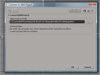
ModTool works by connecting to an existing XNA project and creating an XSI project. This XSI project contains a workspace which contains saved scenes, along with other data used by these scenes. This project is created in a subfolder of the Content folder in your project folder, which means you can include this XSI project in your source control in order to have all artists share a common workspace. To have ModTool connect to your project, click on XNA Game Studio->Connect To XNA Project. In the dialog that appears, browse for the main folder that contains your project. The dialog should say that a project has not been detected at this location, and that one will be created for you. Close this dialog to let ModTool create the project.
Making A Model
Now weAEre ready to make a model that will test out our new content authoring system. First, click on XNA Game Studio->New XNA Scene to create a new scene. Save it in the scenes folder of the new XSI project that was created in your Content folder.
Now that we have a scene, we can add a model to it. We do this by going to XNA Game Studio->Create Model. You should get a cube mesh added to the scene when you do this. You can view this cube in several ways by switching the view mode, which you do by clicking one of the buttons in the bottom left corner of the screen.
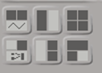 The default is Four Views, which is the top right button. This gives you four different views at a time. The three views in the top left, bottom left and bottom right are typically configured to give you an orthographic (2D) view from a certain direction. The top right view is typically configured to give a 3D view of the scene. Switch the top-right view to ?Explorer? mode (click on the bluish button that says ?Camera? and select Explorer). This view presents the scene graph for your current scene. The scene graph is a hierarchal representation of everything in the scene: meshes, lights, submeshes, etc. YouAEll see that you have your camera, 3 lights, and your model in the scene. If you expand the model node, youAEll see thereAEs a mesh in there: thatAEs our cube that you see in the views. We always want meshes to be part of a model, since anything thatAEs not part of a model wonAEt be exported when we publish the model to our project. Remember this if you ever add additional polygon meshes (you can add any mesh to the model by dragging it to the Model node).
 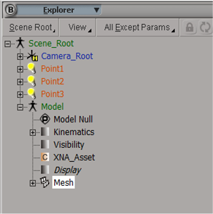 In order to use normal-mapping and other effects that require a tangent basis, we need to add tangents to the mesh. To do this, first select the polygon mesh by expanding the Model node and selecting the ?Mesh? node. Now in the toolbar on the left side of the screen, change it to ?Render? mode by clicking on the purple button on top that says ?Model? and then click on ?Render?. Then click on the ?Property? button, and click on ?Tangent?. Just leave the settings at default in the dialog that pops up. After you do this, there should be a new ?Tangent? node under the Mesh node.
 Now we want to set up the lighting for our scene. We designed our material effect to work with one single directional. This means we canAEt use those point lights; go ahead and delete them from your scene. Now add an Infinite Light to the scene: you can do this by clicking on the ?Primitive? button on the left side of the screen and then going to Light->Infinite. In the dialog that pops up, donAEt worry about anything except for the ?RGB? and Intensity? values in the ?Color? area.
Once the light is added, we can position it and rotate it. Position of course doesnAEt matter for an Infinite Light, since theyAEre global light sources. Direction is what matters, and you can see the direction indicated by the arrow that points away from the light when you select it (you can select the light by clicking on it in the scene graph). To position it, go to translate mode by hitting ?V?, or by clicking on it in the main toolbar, or by clicking on the ?T? in the transform toolbar on the right side of the screen. Then you can drag it around in any of the views. To rotate it, go to rotation mode by hitting ?C?, by clicking on it in the main toolbar, or by clicking on the ?R? in the transform toolbar. You can then rotate it by dragging the mouse on one of the circles, which represent the 3 transform axes. If you need to get a better view of things, go to zoom and pan mode by hitting ?Z? on the keyboard. You can then drag the mouse to move the view, zoom in by clicking the middle mouse button, or zoom out by clicking the right mouse button. If you have the top-right view set to Camera mode, you can also rotate the view by going to orbit mode (hit ?O? on the keyboard) and dragging the mouse.
Go back to the normal ?Selection cursor? by clicking on the big arrow in the top left corner of the screen. Set it to object mode as well. Now select the cube by dragging and making a box that includes it (donAEt select the light). We can now manipulate it in the same way we manipulated the light previously. However for this tutorial, just leave it positioned and oriented where it is. You can also scale the cube: to do this, either go to scaling mode (hit ?X? on the keyboard, or click on the button in the main toolbar or the transform toolbar) and drag the mouse, or set a value directly next to the ?S? in the transform toolbar.
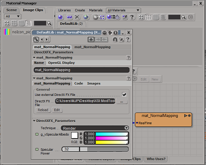
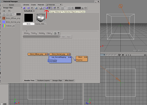
WeAEre now going to assign a material to the mesh. As we said earlier, a material is comprised of one of our material effects, some material parameters, and some textures. Together these all define what the surface of the mesh looks like, and how it responds to lighting. Make sure the mesh is selected, and then go to the Materials Manager by either clicking on ?Materials? in the left-hand toolbar or by going to View->Rendering/Texturing->Materials Manager. In here we have one material already made for us already, but we canAEt use it since it doesnAEt use a DX9 effect. Now weAEll make a new one: to do this, open up an explorer window and go where you saved your mat_NormalMapping effect. With explorer on top, drag the .fx file right into the Material Manager window. You should see a new material appear with the same name as the effect. Double click on it to open up the material properties. On the first tab, we have some properties to play with. The first is the name: name it ?Brick?, since weAEre going to use a brick texture and normal map. In the middle is the .fx file being used; leave that alone, itAEs already set up to use our effect (note that you can click on the ?Reload? button if you ever make changes to the .fx file). At the bottom are the shader properties we defined, complete with the names and controls we specified. You can leave them at the default values for now.
 Move over to the ?Images? tab of the dialog. This is where we set textures for the effect. The dialog should be prompting for two textures: the diffuse map and the normal. Click on the ?new? button to browse for a texture for each: set the diffuse map to ?Brick_Diffuse.png? and the normal map to ?Brick_Normal.png?. We also need to set the texture space for each texture: next to where it says ?Texture Space? click on ?New?, and then select ?Unique UVs (polymesh)?.
 Now we have to assign this new material to our mesh. To do this, first make sure the mesh is selected. Then, assign the material by pressing the button that has a purple sphere with two arrows pointing at a cone (when you hover over the button, the tooltip should say ?Assign material to selected objects or clusters.?) After this you can close the Material Manager.
 In order to see how our material actually looks, we need to turn on the DX9 real-time preview. First make sure the top-right view is set to ?Camera? mode. Then click where it says ?Wireframe? and choose Realtime Shaders->DirectX9 from the dropdown. You should see the mesh in all its normal-mapped glory now.
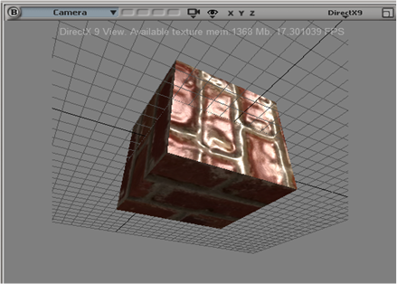
Publishing The Model And Importing It Into The Content Pipeline
To export a model from ModTool, go to XNA Game Studio->Publish Model. In the dialog that pops up, hit the ??? button and browse to the content folder of your project. Pick a name for your model, then hit OK. Now click on ?Consolidate Images and FX Files?, and then click OK (Consolidating images and files copies all textures to Content\Textures, and effects to Content\Effects). You should now have an .xsi model in your Content folder.
Before we can add this new model to the Content Pipeline, we need to add a reference to the Crosswalk content importer. To do this, right-click on the Content project and go to the ?Reference Paths? tab. Here you need to add a path to the Addons\XNAGSE\Application\References\XNA 2.0\ subfolder of your ModTool installation directory. Then add a reference to the importer assembly by right-clicking on References and adding the ?XW4XNA? assembly.
Once youAEve added the importer, we can add the model to your project. Right click on the Content project and click on Add->Existing Item.... Set the dialog to browse for ?all files(*.*)?, and then navigate to the Content folder add your model. Once the model is added, set it to use the Crosswalk Importer by right-clicking and going to Properties, and then selecting the correct importer in the dropdown. Then set it to use the standard Model content processor.
Now that the model is added to the Content project, we can load it in our code through the content pipeline.
protected override void LoadContent() { model = Content.Load("TestModel"); } And finally, weAEre ready to run our game and see our model in action!
Conclusion
By integrating our effects and rendering code with XSI ModTool, weAEve created a Content Authoring pipeline that allows the artists to control their content all the way up to the step of adding it to the gameAEs Content project. This allows both artists and programmers to adopt a streamlined workflow that keeps both groups focused on their main tasks, and also keeps rendering code simplified and data-driven. The techniques used can also be extended to a full material library featuring effect types for a wide variety of rendering scenarios.


