I have been writing an DirectX / OpenGL rendering engine recently. As you may know, DirectX is by default associated with a left-handed coordinate system (LH) and OpenGL with a right-handed system (RH). You can compare both of them in the article title image to the right. You can look at those two systems in another way. If you want to look in a positive direction, for LH, you have Y as UP axis and for RH, you have Z as UP axis. If you dont see it, rotate the RH system in the image. Today, in time of shaders and, you can use one or another in both systems, but you need to take care of few things.
I have calculated both versions of matrices for both systems. I am tired of remembering everything and/or calculating it all over again. For this reason I have created this document, where I summarize needed combinations and some tips & tricks. This is not meant to be a tutorial "How projection works" or "Where those values come from". It is for people who are tired of looking how to convert one system to another or how to convert one API to another. Or it is for those who don't care "why" but they are happy to copy & paste of my equations (however, don't blame me if there is something wrong).
RH system has become some kind of a standard in a computer graphics. However, for my personal purposes, LH system seems more logical to visualise. In my engine, I wanted to give the decision to the user. At the end, my system supports both orientations.
If we looked more closely at DirectX and OpenGL, we can see one important difference in a projection. It doesn't matter if we use LH or RH system, in DirectX projection is mapped to interval [0, 1] while in OpenGL to [-1, 1]. What does that mean? If we take the near clipping plane of a camera, it will be always mapped to 0 for DirectX, but in OpenGL it is more complicated. For LH system, near will be 1, but for RH, it will became -1 (see graphs 5 and 6 in a later section). Of course, we can use DirectX mapping in OpenGL (not the other way), but in that case, we are throwing away half of the depth buffer precision. In the following sections, we will discuss this more closely.
Personally, I think that whoever invented OpenGL depth coordinates must have had a twisted sense for humour. DirectX's solution is far better and easier to understand.
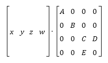
Matrix order used in this article will be row based. All operations will be done in order vector ? matrix (as we can see at (1) ) with indexing from (2).
(1)
(2)
For column based matrix, order of operations will be reversed - matrix ? vector (as we can see at 3). You also need to change elements of matrix, as you can see from example.
(3)
In a time of a fixed function pipeline, that was more problematic than today. In a time of shaders, we may use whatever system and layout we want and just change the order of operations or read values from the different positions in matrices.
World to View transformation
In every transformation pipeline, we need to first transform geometry from the world coordinates to a view (camera) space. After that, you can do a projection transformation. View matrix must use the same system as your final projection, so it must be LR or RH. This section is mentioned only for complete look up, so you know how to transform a point. There will be no additional details for view transformation.
View matrix has the same layout for both of the systems (4)
(4)
Differences are in base vectors and the last row elements calculation. You can see it in table 1.
[table][tr][td][/td][td]LH[/td][td]RH[/td][/tr][tr][td]look[/td][td]|wLook - eye|[/td][td]|eye - wLook|[/td][/tr][tr][td]right[/td][td]|wUp x look|[/td][td]|wUp x look|[/td][/tr][tr][td]up[/td][td]|look x right|[/td][td]|look x right|[/td][/tr][tr][td]A[/td][td]-dot(right,eye)[/td][td]dot(right,eye)[/td][/tr][tr][td]B[/td][td]-dot(up, eye)[/td][td]dot(up, eye)[/td][/tr][tr][td]C[/td][td]-dot(look, eye)[/td][td]dot(look, eye)[/td][/tr][/table]
Table 1: View vectors calculation. wLook is camera lookAt target, eye is camera position and wUp is camera up vector - usually [0,1,0]. "x" stands for a vector product
Perspective projection
For "3D world" rendering, you will probably use a perspective projection. Most of the time (like in 90% of cases) you will need a simplified perspective matrix (with a symmetric viewing volume). Pattern for such a projection matrix can be seen at 5. As you can see, this pattern is symmetric. For column and row major matrices, this simplified pattern will be the same, but values of D and E will be transposed. Be aware of this, it can cause some headaches if you do it the other way and not notice it.
(5)
Now, how projection works. We have an input data in the view space coordinates. From those we need to map them into our screen. Since our screen is 2D (even if we have so called 3D display), we need to map a point to our screen. We take a simple example:
(6)
(7)
where x,y,z,w is an input point ( w is a homogenous coordinate, if we want to "debug" on a paper, the best way is to choose this value as 1.0). Division by ( D ? z ) is performed automatically after vertex shader stage.
From equations 6 we have coordinates of a point on 2D screen. You may see, that those values are not coordinates of pixel (like [756, 653]), but they are in a range [-1, 1] for both axis (in DirectX and also in OpenGL).
From equation 7 we have depth of pixel in range [0, 1] for DirectX and [-1, 1] for OpenGL. This value is used in depth buffer for closer / distant object recognition. Later on, we show how depth values look like.
Those +1 / -1 values, that you will obtain after projection, are known as a normalized device coordinates (NDC). They form a cube, where X and Y axis are in interval [-1, 1] for DirectX and OpenGL. Z axis is more tricky. For DirectX, you have an interval [0, 1] and for OpenGL [-1, 1] (see 2). As you can see now, NDC is a LH system, doesn't matter what input system you have chosen.
Everything, that is inside of this cube, is visible on our screen. Screen is taken as a cube face at Z = 0 (DirectX), Z = 1 (OpenGL LH) or Z = -1 (OpenGL RH). What you see on your screen is basically content of a NDC cube pressed to single plane.
Figure 2: OpenGL (Left) and DirectX (Right) NDC
We summarize computations for LH / RH system and for DirectX and OpenGL in two different tables. Those values are different for LH / RH system and of course for API used. In following sections, you can spot the differences. If you are interested where those values come from, look elsewhere (for example OpenGL matrices are explained here: Link). There are plenty of resources and it will be pointless to go over it again here.
DirectX
Table 2: Projection matrix calculation for DirectX. Input parametrs are: fovY - field of view in Y direction, AR - aspect ratio of screen, n - Z-value of near clipping plane, f - Z-value of far clipping plane
Changing only values at the projection matrix won't work as expected. If we render same scene with same DirectX device settings, we end up with turned scene geometry for one of those matrices. This is caused by depth comparison in depth buffer. To change this settings is a little longer in DirectX, than for OpenGL. You need to call functions in code snippet 1 with values in table 3.
deviceContext->ClearDepthStencilView(depthStencilView, D3D11_CLEAR_DEPTH, 1.0f, 0);
....
depthStencilDesc.DepthFunc = D3D11_COMPARISON_LESS_EQUAL;
device->CreateDepthStencilState(&depthStencilDesc,&depthStencilState);
deviceContext->OMSetDepthStencilState(depthStencilState, 1);
Code 1: Code snippet settings for LH DirectX rendering
[table][tr][td][/td][td]LH[/td][td]RH[/td][/tr][tr][td]D3D11_CLEAR_DEPTH[/td][td]1.0[/td][td]0.0[/td][/tr][tr][td]depthStencilDesc.DepthFunc[/td][td]D3D11_COMPARISON_LESS_EQUAL[/td][td]D3D11_COMPARISON_GREATER_EQUAL[/td][/tr][/table]
Table 3: OpenGL setting for both systems
OpenGL
Table 4: Projection matrix calculation for OpenGL. Input parametrs are: fovY - field of view in Y direction, AR - aspect ratio of screen, n - Z-value of near clipping plane, f - Z-value of far clipping plane
Again, changing only values at the projection matrix won't work as expected. If we render same scene with same OpenGL device settings, we end up with turned scene geometry for one of those matrices. This is caused by depth comparison in depth buffer. We need to change two things as we see in table 5.
[table][tr][td]LH[/td][td]RH[/td][/tr][tr][td]glClearDepth(0)[/td][td]glClearDepth(1)[/td][/tr][tr][td]glDepthFunc(GL_GEQUAL)[/td][td]glDepthFunc(GL_LEQUAL)[/td][/tr][/table]
Table 5: OpenGL setting for both systems
Conclusion
If you set the comparison and depth buffer clear values incorrectly, most of the time, you will end up with result like on the figure 3. Correct scene should look like on the figure 4.
Figure 3: Incorrectly set depth function and clear for current projection
Figure 4: Correctly set depth function and clear for current projection
Using equation 6, we can calculate projected depth for any input value. If we do this for values in interval [near, far], we will get the following result (see image 5 and 6). Notice second graph x-axis. For RH system, we need to change sign of near to -near in order to obtain same results as for LH system. That means in plain language, that for LH we are looking in positive Z direction and for RH we are looking in negative Z direction. In both cases, viewer is located at origin.
Figure 5: Projected depth with DirectX and OpenGL LH matrices (values used for calculation: near = 0.1, far = 1.0)
Figure 6: Projected depth with DirectX and OpenGL RH matrices (values used for calculation: near = -0.1, far = -1.0)
From above graphs, we can see that for the distances near to the camera, there is a good precision in the depth buffer. On the other hand, for larger values the precision is limited. That is not always desired.
One possible solution is to keep your near and far distances together as close as possible. There will be less problems if you use interval [0.1, 10] instead of [0.1, 100]. This is not always possible if we want to render large 3D world enviroments. This issue can be however solved as we show in the next section.
Depth precision
As mentioned before, using a classic perspective projection brings us a limited depth precision. The bigger the distance from viewer, the lower precision we have. This problem is often noticable as flickering pixels in distance.
We can partially solve this by logarithmic depth. We decrease precision for near surroundings, but we have almost linear distribution throughout the depth range. One disadvantage is that logarithm is not working for negative input. Triangles, that are partially visible and have some points behind viewer (negative Z axis), won't be calculated correctly. Shader programs usually won't crash with negative logarithm, but the result is not defined. There are two possible solutions for this problem. You either tesselate your scene to have triangles so small, that the problem won't matter, or you can write your depth in a pixel shader.
Writing depth in a pixel shader brings disadvantage with turned off depth testing for geometry before rasterizing. There could be some performance impact, but you can limit it by doing this trick only for near geometry, that could be affected. That way, you will need a condition in your shader or use different shaders based on geometry distance from viewer.
If you use this modification, be aware of one thing: The depth from vertex shader has range [-1, 1], but gl_FragDepth has range [0, 1]. It's again something OpenGL only, since DirectX has depth in [0, 1] all the time.
For a more detailed explenation, you can read an excellent article at Outtera blog (Link). Equations in their solution are using RH system (they aimed primary for OpenGL). So once again, we show same equation in LH and RH system. Both version are at table 6. This time only for OpenGL, since in DirectX problem can be solved, as proposed in article, by swapping near and far.
[table][tr][td]LH[/td][td]gl_Position.z = (-2.0) * log((-gl_Position.z) * C + 1.0) / log(far * C + 1.0) + 1.0[/td][/tr][tr][td]RH[/td][td]gl_Position.z = (2.0) * log((gl_Position.z) * C + 1.0) / log(far * C + 1.0) - 1.0[/td][/tr][/table]
Table 6:Calculation of new Z coordinate for depth using log. C is linearized component, default value is 1.0, far is camera far plane distance, gl_Position is output value from vertex shader (in perspective projection). You MUST remember to multiply gl_Position.z by gl_Position.w before returning it from shader.
If you have read the Outtera article and looked at my equations, you may notice that I used gl_Position.z in logarithm calculations. I don't know if it is a mistake by Outtera, but with W, I have nearly same results for RH system (as if I used Z), but LH is totally messed up. Plus, W is already linearized depth (distance of point from viewer). So first visible point has W = near and last one has W = far.
If we plot classic vs logarithm depth with equations from 6, we end up with the two following graphs. Red curve is same as in previous chapter, green one is our logarithmic depth.
Figure 7: Projected depth with classic perspective and with logarithmic one in LH (values used for calculation: near = 0.1, far = 1.0, C = 1.0)
Figure 8: Projected depth with classic perspective and with logarithmic one in RH (values used for calculation: near = 0.1, far = 1.0, C = 1.0)
You can observe the effect of both projections (classic and logarithmic one) at this video (rendered with LH projection in OpenGL):
">
Oblique projection
Last section related to a projection will be a little different. So far, we have discussed perspective projection and precision for rendering. In this section, another important aspect will be converted to LH and RH system and to OpenGL / DirectX.
Oblique projection is not some kind of special projection, that makes everything shiny. It is classic perspective projection, only with improved clipping planes. Clipping plane for classic projection is near and far, but here we change near to get different effect. This kind of projection is mostly used for water reflection texture rendering. Of course, we can set clipping plane manually in OpenGL or in DirectX, but that won't work in a mobile version (OpenGL ES), a web version (WebGL) and in DirectX we will need a different set of shaders. Bottom line, solution with clipping plane is possible, but not as clean as oblique projection.
First we need to precompute some data. For a clipping, we need obviously a clipping plane. We need it in our current projective space coordinates. This can be achieved by transforming our plane vector with transposed inverse of the view matrix (we are assuming that the world matrix is set as identity).
Matrix4x4 tmp = Matrix4x4::Invert(viewMatrix);
tmp.Transpose();
Vector4 clipPlane = Vector4::Transform(clipPlane, tmp);
Now calculate the clip-space corner point opposite the clipping plane
float xSign = (clipPlane.X > 0) ? 1.0f : ((clipPlane.X < 0) ? -1.0f : 0.0f);
float ySign = (clipPlane.Y > 0) ? 1.0f : ((clipPlane.Y < 0) ? -1.0f : 0.0f);
Vector4 q = (xSign, ySign, 1, 1);
Transform q into camera space by multiplying it with the inverse of the projection matrix. For a simplified calculation, we have already used an inverted projection matrix.
DirectX
In DirectX system, we need to be careful, because original article is using OpenGL projection space with Z coordinate in range [-1, 1]. This is not possible in DirectX, so we need to change equations and recalculate them with Z in a range [0, 1].
Following solution is valid for LH system:
q.X = q.X / projection[0][0];
q.Y = q.Y / projection[1][1];
q.Z = 1.0f;
q.W = (1.0f - projection[2][2]) / projection[3][2];
float a = q.Z / Vector4::Dot(clipPlane, q);
Vector4 m3 = a * clipPlane;
OpenGL
The following equations can be simplified, if we know handness of our system. Since we want to have an universal solution, I have used a full representation, that is independent on the used sytem.
q.X = q.x / projection[0][0];
q.Y = q.Y / projection[1][1];
q.Z = 1.0 / projection[2][3];
q.W = (1.0 / projection[3][2]) - (projection[2][2] / (projection[2][3] * Matrix.M[3][2]));
float a = (2.0f * projection[2][3] * q.Z) / Vector4::Dot(clipPlane, q);
Vector4 m3 = clipPlane * a;
m3.Z = m3.Z + 1.0f;
In calculation of m3.Z we can use directly addition of value +1.0. If we write separate equations for LH and RH system, we can see why:
LH: m3.Z = m3.Z + projection[2][3]; //([2][3] = +1)
RH: m3.Z = m3.Z - projection[2][3]; //([2][3] = -1)
Final matrix composition
Final composition of the projection matrix is easy. Replace the third column with our calculated vector.
Matrix4x4 res = projection;
res[0][2] = m3.X;
res[1][2] = m3.Y;
res[2][2] = m3.Z;
res[3][2] = m3.W;
Attachment
I have added an Excel file with projection matrices. You can experiment for yourself by changing near and far, or any other parameters and see the differences in depth. This is the same file that I used for creation of posted graphs.
Lengyel, Eric. "Oblique View Frustum Depth Projection and Clipping". Journal of Game Development, Vol. 1, No. 2 (2005), Charles River Media, pp. 5-16. (http://www.terathon.com/code/oblique.html)
So far I only skimmed through and the article looks very interesting, BUT captions of figure 5 & 6 and 7 & 8 are identical. I don't think they are supposed to be
Nice article except for one thing. This sentence:
"As you may know, DirectX uses by default a left-handed coordinate system (LH) and OpenGL uses a right-handed system (RH)"
is not true. Both DX and OGL "internally" has only the concept of normalized device coordinates (NDC) and these coordinates are left-handed for both APIs (Figure 2.). The only difference between APIs that indeed is there is that Z in NDC goes [-1, 1] in OGL and [0, 1] in DX.
There is one misunderstanding - from OpenGL 3.3 and DirectX Graphics 10 there is nothing like "default coordinate system" - every matrix you must set up yourself, and in what coordinate system is entirely programmers concern.
Your DX examples make use of D3D11* constants, yet your external reference to the DirectX documentation (specifically D3DXMatrixPerfpectiveFovLH) is part of the deprecated D3DX utilty library. Modern articles should be referencing the DirectXMath library instead - http://msdn.microsoft.com/en-us/library/hh437833(v=vs.85).aspx
For column based matrix, order of elements is reversed...
In that syntax, it implies the elements of the matrix are reversed, which is incorrect. I understand the intent of your sentence, but you should express it correctly.
Perspective Projection section:
As you can see, this matrix is symmetric.
That is incorrect. The matrix shown is not symmetric. A symmetric matrix is it's own transpose. Because D and E may differ, it is not symmetric.
EDIT: Typo: "(hovewer, don't blame me if there is something wrong)." Should be "however"
I really like this article, except for the confusion of "row" vs "column" conventions in it.
For column based matrix, order of elements is reversed
In that syntax, it implies the elements of the matrix are reversed, which is incorrect. I understand the intent of your sentence, but you should express it correctly.
The actual elements of the matrix themselves do have the be laid out differently. vec * mat is actually mat1x4 * mat4x4 (a "row-vector" multiplied a matrix) mat * vec is actually mat4x4 * mat4x1 (a matrix multiplied by a "column-vector")
Matrix multiplication rules state that you can't have "4x1 * 4x4" or "4x4 * 1x4", because the inner numbers (1 vs 4) do not match, so there is no valid multiplication there.
So if you decide that your vec4's are mat4x1's (you decide to use the column-vector convention), then your vectors must go on the right of the matrix when multiplying. This also means that your matrices will be constructed with the basis vectors stored in the columns of the matrix.
Alternatively, if you decide that your vec4's are mat1x4's (you decide to use the row-vector convention), then your vectors must go on the left of the matrix when multiplying. This also means that your matrices will be constructed with the basis vectors stored in the rows of the matrix.
When he says "column based matrix", he should actually say "a matrix designed to transform column-vectors" or maybe "a column-vector matrix", and then he would be correct.
This is demonstrated in fig (1), where he draws the vector as being a row, or a 1-row x 4-column vector.
I would really like it, if in that section, it was explained that the difference here is in how you are choosing to interpret your vectors, and that it is this decision that in-turn decides how you will order the elements of your matrices.
For column and row major matrices...
This is the wrong terminology. Column and row-major matrices look exactly the same on paper. Column-major / Row-major only affects how you store the actual bytes in RAM. It makes no difference to the maths.
As above, what you're talking about here is matrices designed to transform row-vectors and matrices designed to transform column-vectors.
You can store a "row-vector convention matrix" in either row-major byte ordering or column-major byte ordering!
D3D/GL both support row-vector and column-vector conventions (just by changing which side of the matrix you put the vector on, and how you construct your matrices) and they also support both row-major and column-major byte storage options (with the column_major/row_major keywords inside your shader code).
N.B. Both GL and D3D default to column-major storage for matrices inside shaders.
However, if you're using the row-vector convention, then it's usually more optimal to tell GL/D3D to use row-major byte ordering!
I think it would be good to have a section at the end that explains what row-major vs column-major mean too (that they don't have anything to do with the maths, it's just how we choose to store the values in RAM... like big endian vs little endian!), so that people learning from this will see the whole picture of how they can use matrices in GL and D3D.
There's too many people who think that GL must be column-major or D3D must be row-major, or that D3D requires vectors to be on the left and GL requries them to be on the right, etc, etc... You're totally in control these days! (except for the stupid "Z is from -1 to 1" decision in GL )
For column based matrix, order of elements is reversed
In that syntax, it implies the elements of the matrix are reversed, which is incorrect. I understand the intent of your sentence, but you should express it correctly.
The actual elements of the matrix themselves do have the be laid out differently. vec * mat is actually mat1x4 * mat4x4 (a "row-vector" multiplied a matrix) mat * vec is actually mat4x4 * mat4x1 (a matrix multiplied by a "column-vector")
What you're saying is correct, but I think you missed the intent of the comment. I should've provided the entire sentence, as I was commenting (sorta') out of context:
For column based matrix, order of elements is reversed - matrix · vector .
I think he was trying to say the order of the multiplication of the vector and matrix is reversed, but the English syntax of the sentence implies the order of the matrix elements is reversed.
He should be saying that both those things change. Column-vector convention requires you to reverse the order of multiplication, and if you swap the order of multiplication, you've mathematically transposed your vector, so you also have to mathematically transpose your matrix.
Thank you for pointing out the "misleading" info. I meant it OK, but write it incorrectly.
As for matrix layout in memory. I think, that it is not suitable for this article, because it goes to memory HW specific. This article is using API and math only.
For col / row order. In OpenGL there is (I think) function, that can transpose matrix during upload to shader (but this is messed up in ES version and transpose flag has no effect). In DX, I am not sure if upload can transpose matrix, but in shader I can specify layout of matrix.
The changes you've made look good. You've put a lot of effort into the article, particularly for a technical article that (I assume) is not in your primary language.
Suggestion: "If you have read the Outtera article..." The link to that article appears after you mention it. You should add something like ".. have read the Outtera article (see References).."
As for matrix layout in memory. I think, that it is not suitable for this article, because it goes to memory HW specific.
If by "HW" you mean hardware, be careful, as hardware has nothing to do with it. Perhaps software or firmware? As I'm sure you know, it's a combination of how the matrix is laid out in memory, and how the values in memory are used. However, the scope of the discussion is up to you and seems adequate.
...particularly for a technical article that (I assume) is not in your primary language.
Yes.. my primary language is Czech :) This is more or less first article I have written in English :)
By HW I meant hardware.. but I am not really sure, why matrix is stored in memory in one or the other way :) I never really needed it, since I had no performance issues so far.
What piss me off is some books that says matrix/vector vector/matrix multiplications are projections of one row/column to another row/column just leaving the explanation with a final point and letting the reader think about it. Additional explanations can not only add some things but make you understand the entire subject. Nice article.
As you may know, DirectX uses by default left-handed coordinate system (LH) and OpenGL uses right-handed system (RH). RH system has become some kind of a standard in a computer graphic. However, for my personal purposes, LH system seems more logical to visualise. In this article I summarize differences in matrices and also differences in both APIs (DirectX and OpenGL)
(1)
(2) For column based matrix, order of operations will be reversed - matrix ? vector (as we can see at 3). You also need to change elements of matrix, as you can see from example.
(3) In a time of a fixed function pipeline, that was more problematic than today. In a time of shaders, we may use whatever system and layout we want and just change the order of operations or read values from the different positions in matrices.
(4) Differences are in base vectors and the last row elements calculation. You can see it in table 1. [table][tr][td][/td][td]LH[/td][td]RH[/td][/tr][tr][td]look[/td][td]|wLook - eye|[/td][td]|eye - wLook|[/td][/tr][tr][td]right[/td][td]|wUp x look|[/td][td]|wUp x look|[/td][/tr][tr][td]up[/td][td]|look x right|[/td][td]|look x right|[/td][/tr][tr][td]A[/td][td]-dot(right,eye)[/td][td]dot(right,eye)[/td][/tr][tr][td]B[/td][td]-dot(up, eye)[/td][td]dot(up, eye)[/td][/tr][tr][td]C[/td][td]-dot(look, eye)[/td][td]dot(look, eye)[/td][/tr][/table] Table 1: View vectors calculation. wLook is camera lookAt target, eye is camera position and wUp is camera up vector - usually [0,1,0]. "x" stands for a vector product
(5) Now, how projection works. We have an input data in the view space coordinates. From those we need to map them into our screen. Since our screen is 2D (even if we have so called 3D display), we need to map a point to our screen. We take a simple example:
(6)
(7) where x,y,z,w is an input point ( w is a homogenous coordinate, if we want to "debug" on a paper, the best way is to choose this value as 1.0). Division by ( D ? z ) is performed automatically after vertex shader stage. From equations 6 we have coordinates of a point on 2D screen. You may see, that those values are not coordinates of pixel (like [756, 653]), but they are in a range [-1, 1] for both axis (in DirectX and also in OpenGL). From equation 7 we have depth of pixel in range [0, 1] for DirectX and [-1, 1] for OpenGL. This value is used in depth buffer for closer / distant object recognition. Later on, we show how depth values look like. Those +1 / -1 values, that you will obtain after projection, are known as a normalized device coordinates (NDC). They form a cube, where X and Y axis are in interval [-1, 1] for DirectX and OpenGL. Z axis is more tricky. For DirectX, you have an interval [0, 1] and for OpenGL [-1, 1] (see 2). As you can see now, NDC is a LH system, doesn't matter what input system you have chosen. Everything, that is inside of this cube, is visible on our screen. Screen is taken as a cube face at Z = 0 (DirectX), Z = 1 (OpenGL LH) or Z = -1 (OpenGL RH). What you see on your screen is basically content of a NDC cube pressed to single plane.
Figure 2: OpenGL (Left) and DirectX (Right) NDC We summarize computations for LH / RH system and for DirectX and OpenGL in two different tables. Those values are different for LH / RH system and of course for API used. In following sections, you can spot the differences. If you are interested where those values come from, look elsewhere (for example OpenGL matrices are explained here: Link). There are plenty of resources and it will be pointless to go over it again here. DirectX
Table 2: Projection matrix calculation for DirectX. Input parametrs are: fovY - field of view in Y direction, AR - aspect ratio of screen, n - Z-value of near clipping plane, f - Z-value of far clipping plane Changing only values at the projection matrix won't work as expected. If we render same scene with same DirectX device settings, we end up with turned scene geometry for one of those matrices. This is caused by depth comparison in depth buffer. To change this settings is a little longer in DirectX, than for OpenGL. You need to call functions in code snippet 1 with values in table 3.
Table 4: Projection matrix calculation for OpenGL. Input parametrs are: fovY - field of view in Y direction, AR - aspect ratio of screen, n - Z-value of near clipping plane, f - Z-value of far clipping plane Again, changing only values at the projection matrix won't work as expected. If we render same scene with same OpenGL device settings, we end up with turned scene geometry for one of those matrices. This is caused by depth comparison in depth buffer. We need to change two things as we see in table 5. [table][tr][td]LH[/td][td]RH[/td][/tr][tr][td]glClearDepth(0)[/td][td]glClearDepth(1)[/td][/tr][tr][td]glDepthFunc(GL_GEQUAL)[/td][td]glDepthFunc(GL_LEQUAL)[/td][/tr][/table] Table 5: OpenGL setting for both systems Conclusion If you set the comparison and depth buffer clear values incorrectly, most of the time, you will end up with result like on the figure 3. Correct scene should look like on the figure 4.
Figure 3: Incorrectly set depth function and clear for current projection
Figure 4: Correctly set depth function and clear for current projection Using equation 6, we can calculate projected depth for any input value. If we do this for values in interval [near, far], we will get the following result (see image 5 and 6). Notice second graph x-axis. For RH system, we need to change sign of near to -near in order to obtain same results as for LH system. That means in plain language, that for LH we are looking in positive Z direction and for RH we are looking in negative Z direction. In both cases, viewer is located at origin.
Figure 5: Projected depth with DirectX and OpenGL LH matrices (values used for calculation: near = 0.1, far = 1.0)
Figure 6: Projected depth with DirectX and OpenGL RH matrices (values used for calculation: near = -0.1, far = -1.0) From above graphs, we can see that for the distances near to the camera, there is a good precision in the depth buffer. On the other hand, for larger values the precision is limited. That is not always desired. One possible solution is to keep your near and far distances together as close as possible. There will be less problems if you use interval [0.1, 10] instead of [0.1, 100]. This is not always possible if we want to render large 3D world enviroments. This issue can be however solved as we show in the next section.
Figure 7: Projected depth with classic perspective and with logarithmic one in LH (values used for calculation: near = 0.1, far = 1.0, C = 1.0)
Figure 8: Projected depth with classic perspective and with logarithmic one in RH (values used for calculation: near = 0.1, far = 1.0, C = 1.0) You can observe the effect of both projections (classic and logarithmic one) at this video (rendered with LH projection in OpenGL):

")


 (except for the stupid "Z is from -1 to 1" decision in GL
  )
)

Typo in (3). I think m22 should be look.z
Other than that it's a quite interesting article