This rendering algorithm is based on the SIGGRAPH93 publication: "Display of The Earth Taking into Account Atmospheric Scattering" by Tomoyuki Nishita, Takao Sirai, Katsumi Tadamura, and Eihachiro Nakamae (which I will refer to as Nishita for the rest of the article). This publication is included with this article here. If you haven't read it, please read it before you read this article. You don't need to understand the math in it, but you do need to understand the concepts.
Oh, and read the README.TXT before you run the prototype. If someone sends me an email with a question that was answered in the README.TXT, the next version I publish will open it automatically for you every time you launch the program, and it will crash if it can't find the file. ?
Disclaimer: If all you need is a pretty skybox, this article is not what you're looking for. If you need an animated skybox with awesome sunsets and clouds, this article still probably isn't what you're looking for (but it might give you some ideas).
I wrote this article because I've wanted to implement realistic real-time atmospheric scattering for my procedural planet renderer for a while now.
Before I started this, I saw a lot of questions about atmospheric scattering on the forums. I also saw a lot of great answers, but they weren't really the answers I needed. Unfortunately, being able to accurately render any type of planet or moon from any viewpoint with any type of atmosphere means you can't cut many corners. You can't assume that the density of the atmosphere is the same everywhere. You also can't assume that the scattering constants, or their dependence on wavelength, will be the same everywhere. This disqualifies most of the really useful optimizations before you even get started.
The demo, which I am providing with complete source code, doesn't render a planet and it doesn't render a sun. It currently renders the empty atmosphere shell, much like Figure 6 in Nishita's publication. It renders the outside of an inner sphere to show the scattering reflecting off the planet's surface, and the inside of an outer sphere to show the scattering that just passes through the atmosphere. It implements both Rayleigh and Mie scattering, and all of the constants can be modified at runtime within the demo.
The Problem
The primary optimization Nishita described was to pre-calculate a lookup table of the optical length between the sun and every point in the atmosphere. This is possible primarily because the sun is so far away that the sun's rays can be considered parallel. Unfortunately, this leaves you with the costly calculations of determining the optical length between the camera and every point in the atmosphere, if and where each ray from the camera enters the shadow of the planet, and the nasty integral over some expensive exponential equation that involves both optical depths (which are themselves nasty integrals over some other expensive exponential equation). One of the nested nasty integrals is taken care of by the lookup table, but the other one is not.
Math refresher: For those of you who haven't learned (or don't remember) what an integral is, don't worry about it. In its most basic form, an integral is simply a sum of values across a range. Programmers write loops that calculate sums all the time, and that's one way to solve an integral equation. To calculate the approximate optical depth along a ray, you simply break the ray up into a bunch of smaller "sample" rays, then loop through the sample rays summing the results of the equation (density * length) for each of them. The smaller the sample rays are, the more accurate your results are.
Now I'll explain just how painful these calculations are, even using Nishita's optimization. If you take 10 sample rays and the problem is nested, then you have to solve 10*10 expensive math equations per vertex (10*20 without Nishita's optimization). Multiply that by 3 because you need to calculate each one separately for each color channel (red, green, and blue). Multiply everything again by two if you're doing both Rayleigh and Mie scattering. We're up to 600 equations per vertex now, and don't forget to determine whether the ray went into the planet's shadow. If you want this to be real-time, it's easy to figure out before you start coding that this approach won't work.
A Better Lookup Table
By tweaking the optical length lookup table just a little, it can be used for both optical length calculations (one to the light source and one to the camera), it can tell you what the density is at any point, and it can tell you when a ray enters the shadow of the planet. This leaves you with one integral which, as long as your lookup is precise enough, 3 or 4 samples seems to be sufficient to make it look good. I've only implemented a prototype so far, but it runs in real-time with 100% of the calculations done on the CPU and using a fairly sloppy brute-force rendering method. It runs between 50-100 FPS on my system, and it should be easy to make it go a good bit faster.
The lookup table I generate is a bit different from the one described in the publication. It fits nicely into a 2D texture map in case someone wants to try to use it in vertex/pixel shaders. It uses two channels for Rayleigh scattering, and two channels for Mie scattering. For all channels, the horizontal axis represents the height of a sample point, and the vertical axis represents the angle of a sample ray from vertical. The angle goes all the way to 180 degrees (straight down) because viewpoints above the ground can see farther than 90 degrees at the horizon.
There are two ways to interpret the result if the ray intersects the planet on its way to the outer edge of the atmosphere. If you want the optical legth to the sun (or other light source), then the optical length should be zero because it means the sample point is in the shadow of the planet. If you want the optical length to the camera, then you have to pretend like the ray didn't hit the planet. This is because many triangles at the horizon have one or two vertices behind the planet, and making those vertices black really messes up your horizon.
Channel 1 - If the ray hits the planet, this value is 0. Otherwise, this value contains the Rayleigh scale density for this height.
Channel 2 - The Rayleigh scale optical length from the sample point along the sample ray.
Channel 3 - The same as channel 1, but using the Mie scale density.
Channel 4 - The same as channel 2, but using the Mie scale optical length.
The lookup table is generated in CPixelBuffer::MakeOpticalDepthBuffer(), and it is commented. I hope this description and the comments make it clear what it's doing.
Using the Lookup Table
Even though the use of this table seemed intuitive when I first came up with the idea, I ran into a surprising number of problems implementing it. Like Sir Robin exclaiming "Hey! That's easy.", I was snatched off my fake horse (so to speak). Luckily I landed on something soft and was able to work out all of the problems.
Unfortunately I still haven't figured out how to avoid the outer integral without creating a 4-D lookup table. That 4-D lookup table would also be less flexible, and I'd need a different one for each planet or moon that had an atmosphere. Since I can't get around it, this means I have to trace the ray from the camera to each vertex, break it up into sample rays and calculate the scattering across each sample ray.
For each sample ray, calculate the center point and determine its height and the angle to the light source. Perform a lookup in the table using that height and angle. If channel 1 is 0, then this sample is in shadow and you can skip this sample ray and move on to the next one. Otherwise store the value of channel 1 as the atmospheric density at the sample point, and store the value of channel 2 as the optical depth from the sample ray to the light source.
Now it's time to determine the optical length to the camera for the sample ray, and this is where things get a bit tricky. It's easy if the camera is in space because it works just like the light source. Calculate the height of the sample point and the angle to the camera, perform a lookup in the table, and add channel 2 to the optical depth you stored from the first lookup.
When the camera is inside the atmosphere, the lookup table breaks. This is because it stores optical depths from one point inside the atmosphere to the top of the atmosphere. It does not store optical depths from one point inside the atmosphere to another point inside the atmosphere. To complicate matters a bit more, when a point is above the camera the angle to the camera points down, putting you in the wrong spot in your lookup buffer.
The answer to the first problem is to do two lookups (one for the sample point and one for the camera), and subtract one from the other. The answer to the second problem is to reverse the ray direction for both lookups when the target vertex is higher than the camera. To keep the code clean, when the camera is in space, you can treat it like it's at the top of the atmosphere and like it's always above any vertex being rendered in the atmosphere. The pseudo-code looks something like this:
if (camera is above vertex)
    camera_lookup = lookup(camera_height, angle to camera);
else
    camera_lookup = lookup(camera_height, angle from camera);

for(each sample ray)
{
    light_source_lookup = lookup(sample_height, angle to light source);
    density = light_source_lookup(channel 1);

    if (density > 0)
    {
	    density *= sample_ray_length;
	    optical_depth = light_source_lookup(channel 2);

        if (camera is above vertex)
        {
            sample_point_lookup = lookup(sample_height, angle to camera);
            optical_depth += sample_point_lookup(channel 2) - camera_lookup(channel 2);
        }
        else
        {
            sample_point_lookup = lookup(sample_height, angle from camera);
            optical_depth += camera_lookup(channel 2) - sample_point_lookup(channel 2);
        }

        calculate_scattering_attenuation;
    }
}

calculate_vertex_color;
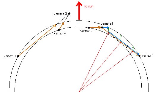
Figure 1
This figure illustrates a few sample camera points and vertices, with one ray broken up into three sample rays. The orange lines indicate the rays that must be traversed for scattering calculations and the ray direction for calculating angles. The blue lines indicate the part you have to subtract from the first lookup in the optical depth table. For the ray broken into sample rays, the blue line is only shown for the first sample point. The red lines pointing to each sample point make it easier to see the different heights and angles for each sample point. The green lines going from each sample point make it easier to see how the height and angle affects the optical depth to the light source.
The real code for the pseudo-code above is in CGameEngine::SetColor(), and it is commented. I hope the pseudo-code and figure make it clear what the code is doing. If not, I'm sure I'll hear about it on the forums. ![]()
Optimizations
There are a lot of optimizations you could make to this to make it run faster. To start with, a number of optimizations can be made to the SetColor() function. Caching variables and creating a few 1D lookup tables could speed up a number of the calculations. For instance, the phase function calculations could be replaced with a 1D lookup table, with one channel for Rayleigh and one for Mie. The same could be done for the attenuation calculation using three channels to avoid calling exp() 3 times. I'm sure there are others.
It would also be a good idea to improve the hidden surface removal to avoid calling CGameEngine::SetColor() so many times. A dynamic level-of-detail implementation could also help minimize the number of calls to SetColor().
If that's not enough, you can use frame coherence to avoid re-calculating the colors for every vertex for every frame. You only need to update a vertex color when the camera or the light source moves far enough relative to that vertex to introduce a noticeable error in the color. Actually, if you keep the atmosphere from rotating with the planet (keep one side pointed at the light source), you only have to worry about the camera moving.
Some of the work for this could be offloaded to the GPU. If nothing else, the conversion from the integral sums to the color values themselves could be done in a vertex shader. If you pushed the phase function calculation into a pixel shader, you would get much smoother gradients, which would look much better for the Mie scattering (which looks terrible with low tesselation).
Last but not least, I hope that someone out there comes up with an even better way to do this. Although I'm proud of what I've accomplished given what I've been able to find online, I keep thinking there must be an even better way to do this, perhaps involving a 3-D buffer or multiple 2-D buffers.
Other Thoughts
I am also working on real-time volumetric clouds, but I don't have them running real-time across a whole planet yet. Once I do that, it shouldn't be difficult to apply the atmospheric scattering to them to get those beautiful sunset colors. What will be difficult will be sampling the cloud shadow buffer in my atmospheric scattering loop, as that should give some cool shafts of light. It sounds a bit too close to ray-tracing though, and I'm not sure I'll be able to make it fast.
Oh, and before you ask, the "ground" scattering looks way off when the camera is close to the ground because the vertices are so far apart in these brute-force spheres. The ground should look black (i.e. almost no light scattered in) directly beneath your feet because it's so close, but it won't if the nearest vertex is far away. With a dynamic LOD scheme like my planet renderer uses, it should look fine.


I like it!