Particle Systems
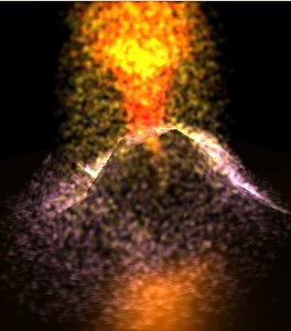 In computer graphics, particle systems represent an unstable side of nature: substances that donAEt have a surface and change rapidly over time, like rain, fire, fog, sparks. Every game engine has some kind of a sub-system for processing the particles, ideally exposing the full set of the functionality in the native particle editor. Until now, when OpenGL 3 and GPGPU tools gained wide support, particle engines were limited to 2[sup]10[/sup]-2[sup]13[/sup] particles being processed simultaneously. This article describes an advanced GPU-only particle engine structure. The technologies described are designed in terms of OpenGL core profile, but can be ported to Direct3D 10 as well. The reader should have a general understanding of particle systems, OpenGL-3 pipeline and modern high-level shading languages.
 Traditional Approach
struct Particle { //attributes Vector3 pos, speed; float size; }; class ParticleSystem { std::vector array; void init(unsigned num); void step(float delta); }; The step() which updates the particle state including death and birth events is called all the time. The particle data is sent to GPU memory (represented by the buffer object) either by the direct data transfer call (glBuffer[Sub]Data(), glTexImage*) or implicitly by releasing of the locked memory (glUnmapBuffer) on every frame.
Point Sprites
The GPU is designed to process triangles, so each particle is generally drawn as a triangle (3 vertices) or a quad (2 triangles, 4 vertices). Point Sprite extension provides the functionality to generate the quad automatically on GPU from a given center coordinate and a size (glPointSize). When drawing points (GL_POINTS) in GL3+ context, it is enabled by default. An obvious advantage here is a great reduction in bandwidth load: sending 1 point data instead of 3-4 per particle. A downside is: the quad is generated in screen space and so can not be rotated and projected by the GL pipeline. Some particle systems work with symmetric forms (smoke, snow, fluids) and fit the point sprite model pretty well. In order to draw more complex primitives (like a rotated triangle), one can simulate a virtual viewport inside the point sprite quad area, implementing the rotation/projection transformations in the fragment shader and discarding unused area pixels.
Modern Approach
 Most particles donAEt require processing of self-interactions (rain, fire, fog). This makes the main particle processing loop iterations independent and thus easy to run in parallel. The GPU can handle such processing in a more efficient way compared to the CPU, as it was originally designed for parallel computations of vertices and fragments. One of the features that made its way into the GL 3.1 core profile is Transform Feedback. It allows one to turn off the graphics rasterizer (optionally) and write transformed vertex data back into buffer objects. By using this technology and matching the input/output format of the vertex shader one can process particle data entirely on GPU. It will be stored in buffer objects, available for drawing right away. The difference from the CPU approach here is the necessity in the separate output buffer, as itAEs not possible to transform the data in-place on the GPU. The sequence of operations goes as follows:
 init A; A->B; B->A; ... draw A ... ; A->B; ...
It is even possible to initialize particle data state right on the GPU. There is a special shader value gl_VertexID that allows us to distinguish different particles in a shader (only the initial values are set, so no input data is given at this stage).
It is reasonable to do particle processing and drawing separately with different frequencies. Thus the rasterizer is disabled when updating the data (GL_RASTERIZER_DISCARD). However, there is an option to combine these stages by enabling the rasterizer - and letting the transformed attributes to be drawn on the spot. This way is a bit faster, but much less scalable for the general purpose. It can be used for demos.
Implementation Details
Birth and Death
It is impossible to allocate memory in the shader, so the chunk of memory which is initially allocated for the particle data storage should already contain all possible particles that can co-exist. The allocated number of particles = capacity of the system = maximum theoretical number of particles living at the same time. The boolean flag isAlive can be encoded into one of the particle attributes (like particle moment of birth, where value <0 means that the particle is dead). The decisions of birth and death are made right inside the vertex shader that is responsible for particle update processing:
if(isAlive) //update() returns 0 for dead particles isAlive = update(); else if( born_ready() ) //reset() gives initial state to a new-born isAlive = reset();
Managing Multiple Emitters
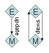 If there are several emitters of the same particle format and capacity, they can share a single temporary buffer for data processing. It can be implemented by a ParticleManager class that contains the same data as each of the emitters E0,E1,E2,... The data flow is the following: Ei -> M (processing); Ei <> M (swap data)
 Each emitter has the current copy of the particle data at any moment.
Conclusion
The proposed technology of particle systems processing provides a more efficient utilization of the GPU power, reduces the system bandwidth load and frees CPU memory for other tasks like physics and AI.
Simulating Fur Strands
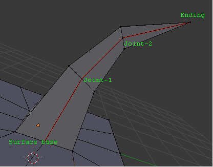 In the previous page the technique of modeling particle systems on the GPU was covered. Now weAEll talk about an extension to that technique that allows modeling of fur strands. In addition to the previous pre-requisites, we expect the readerAEs understanding of Texture Buffer Objects, Render Target concept and spatial transformations, including quaternion operations. The Blender representation of the strand that needs to be simulated consists of the fixed number of joints, connected by straight lines. A brief description can be found in Particle System and Fur Rendering, but the best source of knowledge is Blender itself. This model was chosen in order to have a possibility to edit hair in Blender and then easily move it into an engine. The export script into the KRI engine format has support for particles and hair, including physics and rendering parameters.
 Definition: fur layer - a set of points joint (see picture) across all of the strands of a given surface.
Emit Sources
General particle data source is a mesh. Its geometry can be accessed directly from the shader that initializes the particle data on the birth event. This fact allows efficient emission of particles from the vertices or even the whole surface of a mesh, which can also be skinned and morphed at the same time.
Emit From Vertices
The way to the vertices lies through the Texture Buffer Object concept. It is required to bind the mesh data as TBO and sample from it in the particle processing shader, extracting the position and orientation (see Appendix A) of a randomly chosen vertex. Once the vertex is extracted, it is possible to apply the initial direction of a particle in the constructed basis to get the speed and copy the position. uniform samplerBuffer unit_vertex, unit_quat; int cord = int( random() * textureSize(unit_vertex) ); vec3 pos = texelFetch(unit_vertex, cord).xyz; vec4 quat = texelFetch(unit_quat, cord);
Emit From Faces
In order to access the mesh surface data in the random pattern, it is necessary to bake it first into a UV texture. For each texel in the UV space the position and orientation (as a quaternion) of the point in the world space are stored, writing into 2 Rgba8 textures. In the vertex shader, the position is constructed from the texture coordinate: in vec2 at_tex0; //texture coordinate gl_Position = vec4( 2.0*at_tex0 - vec2(1.0), 0.0,1.0 ); When the textures are ready, a random sample is taken from them in the same way it was done for the vertices emitter case. Note: UV texture defines the amount and density of the grown fur, hence giving full control to the artist.
Fur Extension
Each fur layer is simulated as a separate particle emitter, all layers belong to the same particle manager. Capacity of that system equals the number of fur strands that need to be modelled. The strand joint particle is required to store at least position and speed attributes. There are 3 issues arising from this point of view:
Making a Layer Dependent on Previous Layers
Definition: fake attribute - a particle attribute whose value is not stored per particle instance but rather taken from some external source (e.g. another particle emitter). The previous layer position is required in order to determine the current strand direction.
One layer before previous position is required for estimating the aestraightAE direction and thus the current deviation. Both Pos(L-1) and Pos(L-2) are transmitted as fake attributes for processing of the current layer, where:
Pos(x) = position of the strand joint of layer aexAE,
aeLae = current layer id (0