This article describes a method of animating skinned meshes using matrices. Games often use animated characters which walk, run, shoot, etc. Those animated characters are often rendered using an animated skinned mesh. Such skinned meshes and animation sequences can be created using several modeling programs (such as Blender). Those models can then be exported in a format compatible with various API import routines. This article provides an overview of the animation process in the final application after that data has been imported ("loaded", "read in".) The process of modeling, rigging, animation, exporting or importing is not discussed.
Notes:
------------------------------
For conciseness, the term SRT is used as an abbreviation for the process of applying, in order, a Scale operation, a Rotatation operation, and a Translate operation.
For most applications, that is the order in which those operations should be performed to achieve the expected results. The order of matrix multiplication varies among APIs.
The order of matrix-matrix multiplications and vector-matrix multiplications shown herein is that used by DirectX and assumes "row-vector" matrices.
For instance:
// order of multiplication in DirectX
FinalVector = vector * ScaleMat * RotationMat * TranslationMat
In OpenGL, the order of those multiplications may be reversed, as OpenGL applications commonly use "column-vector" matrices. That is, to achieve a vector scaling followed by a rotation, followed by a translation, the equation would be:
// order of multiplication in OpenGL
FinalVector = TranslationMat * RotationMat * ScaleMat * vector
N.B., the mathematical end result of the operation is the same in both DirectX and OpenGL - a vector position that has been scaled first, rotated, and translated, in that order.
Animating a skinned mesh relies on the principle that scaling, rotating and translating (SRT) a position in space can be represented by a matrix. Further, an ordered sequence of SRTs can be represented by a single matrix resulting from multiplying a sequence of matrices, each representing an individual SRT. E.g., final-matrix = SRTmatrix1(rot1 followed by trans1) * SRTmatrix2( rot2 followed by trans2). In that example, the final-matrix, when applied to a position, would result in a rotation of the position by rot1, followed by a translation (trans1), followed by a rotation (rot2), followed by a translation (trans2).
The Components of an Animated Skinned Mesh
"Animated" means moving or appearing to move as if alive. "Skinned" means a mesh with a frame or "bone" hierarchy with which mesh vertices can be rendered at various positions in space to simulate movement - such as running, waving, etc. "Mesh" means a collection of vertices (positions in space) forming faces (triangles, quads) to be drawn, perhaps in different orientations (SRTs).
What's a "bone?"
The term "frame" is used because it refers to a mathematical "frame of reference," or an orientation (SRT) with respect to (for instance) the world. The term "bone" is frequently used instead of "frame" because the concept can be used to simulate how a bone would cause the skin around it to move. If an arm is raised, the bones of the arm cause the skin surrounding the bone to move upward. However, the term "bone" implies a length associated with it. Bone frames used in the type of animation described in this article do not have an associated length. Though the "length" of a bone might be thought of as the distance between a bone and one of its child bones (lower arm bone with a hand bone 13 inches away), a bone as used for skinning meshes may have more than one child bone, and those child bones need not be at the same distance from the parent. For instance, it is not unusual for a human character to have a neck bone, and right and left shoulder bones, all being children of a spine bone. Those child bones need not be at the same distance to the spine bone.
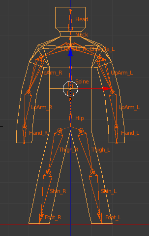
In a common frame hierarchy, every frame except the root frame has a parent frame. That allows the entire hierarchy to be scaled, rotated and translated with a single matrix. Take a look at the frame hierarchy below. An indentation of a frame name immediately below another frame indicates a child-parent relationship. E.g., the Hip frame is a child of the root frame. The Left Thigh frame is a child of the Hip frame. Further notice that the Spine frame is at the same level of indentation as the Hip frame. That indicates that the Spine is a sibling of the Hip frame, and a child of the Root frame. If the root frame has an SRT applied to it, that SRT propagates down the entire tree, from child to child. E.g., if the root frame is rotated, the hip is rotated by the root frame, the left thigh is rotated by the hip, etc. Similarly, if the root frame is translated, the entire hierarchy is translated. In an animated skinned mesh, SRT matrices may be applied to any frame in the hierarchy. That SRT will be propagated only to the frame's children, through the frame's children to their children, etc. There is no effect on the parent of that frame. In that way, the Left Upper Arm can be rotated upward in a waving motion. The Left Lower Arm and Left Hand will rotate upward also. However, the Left Clavicle, the Spine and the Root frame will not move, and the waving motion will appear as one might expect. An example frame hierarchy Root frame
Hip
Left Thigh
Left Shin
Left Foot
Right Thigh
Right Shin
Right Foot
Spine
Neck
Head
Left Clavicle
Left Upper Arm
Left Lower Arm
Left Hand
Right Clavicle
Right Upper Arm
Right Lower Arm
Right Hand
It should be noted that other objects such as building cranes, or an office chair where the seat and chair back can rotate independently, can be animated in precisely the same fashion. However, the advantage of the skinning process is that the mesh, with proper bone-weighting of the vertices, can appear to deform smoothly as if it were bending in a non-linear fashion. For instance, when an arm is raised, it appears that the skin between the chest and the shoulder stretches. If a hand is rotated, it appears that the skin between the lower arm and the hand stretches and rotates. This article discusses frames (bones) which are implemented in skinned mesh animation with matrices. Each frame, during the animation process, has several matrices associated with it in the course of a single render cycle. Each bone, for instance, has an "offset" matrix related to that bone's SRT with respect to the root frame; each bone has a set of animation "keys" (matrices) used to orient the bone with respect to its parent bone during animation; each bone has an animation matrix and a "final" matrix. That may appear to be complicated, but can be understood by considering the process one step at a time.
The Frame Structure
Before continuing, consider an example of how a "frame" may actually be represented in code. Pseudo-code is used which looks quite like C or C++, but hopefully can be converted to other languages a programmer may be more comfortable with. struct Frame { string Name; // the frame or "bone" name Matrix TransformationMatrix; // to be used for local animation matrix MeshContainer MeshData; // perhaps only one or two frames will have mesh data FrameArray Children; // pointers or references to each child frame of this frame Matrix ToParent; // the local transform from bone-space to bone's parent-space Matrix ToRoot; // from bone-space to root-frame space }; Normally, each frame has a name. In the hierarchy above, all of the frames (Root, Hip, Left Thigh, etc.) would each have a frame like the above, and Name would correspond to the name in the hierarchy. The other members of the frame structure and their uses will be described in more detail later in the article.
Animation Data and How It's Used
The data below indicates what information is needed to animate a skinned mesh. Not all of the data is contained in the frame hierarchy structures. Generally, the frame hierarchy contains data describing the bone structure, the mesh structure, and relationships between bones and mesh vertices. All that data represents the skinned mesh in a rest pose. Animation data is commonly stored and accessed separately. That is intentional as a set of animation data represents a single action for the mesh, e.g., "walk," "run," etc. There may be more than one of those animation sets, but each set can be used to animate the same frame hierarchy. The total data needed for animation of a skinned mesh is comprised of: * A mesh in a "pose" or "rest" position, possibly contained in a frame. * A frame hierarchy. The hierarchy is normally comprised of:
- a root frame - for each frame, a list or array of pointers to that frame's children's frames. - for each frame, an indication if the frame contains a mesh - for each frame, one or more matrices for storing frame-related SRTs
* various arrays of influence bone data
- for each influence bone, an offset matrix - for each influence bone, an array of vertex indices and weights for the vertices which the bone "influences."
* an array of animations. Each animation is comprised of:
- an indication of which bone the animation applies to - an array of "keys." Each key is comprised of:
- a tick count indicating the "time" in the animation sequence the key applies to - a matrix (or a set of individual SRTs) for that tick count.
* An indication of how many ticks should be processed per second (ticks-per-second)
in some cases, all that data may not be contained in the data file(s) for the mesh to be animated. Some formats, for instance, do not provide an offset matrix. That matrix can be calculated from other information. The offset matrix is discussed below.
The Mesh
The mesh data is comprised of an array of vertices, positions relative to the root frame (or to a frame containing the mesh), along with other data such as normal vectors, texture coordinates, etc. The vertex positions are normally in a pose or rest position. I.e., not in an animated position. If the mesh data is the child of a frame other than the root frame, the skinning process must account for that. That is considered in the discussion of the Offset Matrix below. Animated meshes are most often rendered in a shader or effect. Those shaders expect as input vertex information in a particular order during rendering. The process of converting per-vertex data as-imported to a vertex format compatible with a particular shader or effect is beyond the scope of this article.
Initializing The Data
With an idea of the data that's needed for skinned mesh animation, here's an overview of the process that makes animation possible. A lot of the required data is loaded from an external file. A frame hierarchy is created and, referring to the Frame structure above, filled with at least the following data: Name, MeshData (not all frames), Children (if the frame has any), and the ToParent matrix. The ToRoot matrix for each frame is initialized as follows:
// given this function ...
function CalcToRootMatrix( Frame frame, Matrix parentMatrix )
{
	// transform from frame-space to root-frame-space through the parent's ToRoot matrix
	frame.ToRoot = frame.ToParent * parentMatrix;
	for each Child in frame:
		CalcToRootMatrix( Child, frame.ToRoot );
	}

	// ... calculate all the Frame ToRoot matrices
	CalcToRootMatrix( RootFrame, IdentityMatrix );

	// the root frame has no parent
Recursive functions such as CalcToRootMatrix can be a little difficult to grasp at first. However, the following expansion of the process will hopefully show what's happening:
frame.ToRoot = frame.ToParent * frame-parent.ToParent * frame-parent-parent.ToParent * ... * RootFrame.ToRoot Some of the data needed for animation will apply only to those bones which influence mesh vertices. During the rendering process, that data will be accessed by bone index, not by bone name. A SkinInfo object or function, using the array of bone influence data, provides the number of influence bones in that array [ SkinInfo.NumBones() ] and can return the bone's name given the bone's index [ SkinInfo.GetBoneName(boneIndex) ].
A more detailed decription of SkinInfo is beyond the scope of this article. The initialization process also creates an array of "offset" matrices, a matrix for each influence bone. As not all frames in the hierarchy influence vertices, that array is smaller than the number of frames, and is sized to hold SkinInfo.NumBones().
A Slight Diversion from the Initialization Process
Though not part of the initialization process, understanding what the frame's TransformationMatrix is used for will help to understand why an array of "offset" matrices is needed for animation. The Frame TransformationMatrix is filled each render cycle using the animation arrays. An "animation controller" object or function uses the animation data to calculate those transforms and stores the result in each frame's TransformationMatrix.
That matrix transforms vertices from a bone's reference frame to the bone's parent's animated reference frame. Similar to the ToParent matrix, which applies to the "pose" position, this matrix applies to an "animated" position - how the mesh will appear during animation. One can think of this matrix as being "how the bone will change from pose position to animated position." Consider the following situation. During an animation, the character's hand is to be rotated slightly by an influence bone.
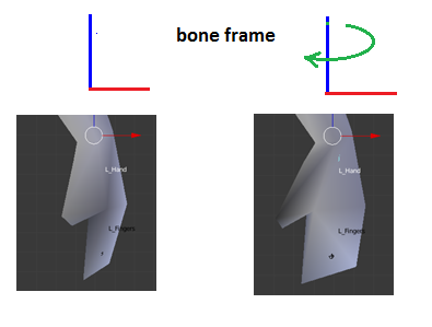
Bone-frame Rotation If the bone's TransformationMatrix is applied to a vertex which it influences, the vertex position, being in root-frame space, will rotate instead in root-frame space.
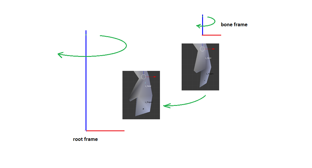
Yet another matrix is needed which will transform the vertex into bone-space so the rotation can be applied properly. Enter..
Back into Initialization - The Offset Matrix
The offset matrix is already provided by many file formats and explicit calculation of the offset matrix for each influence bone is unnecessary. The information below is provided for the purpose of understanding the purpose of the offset matrix.
For a vertex to be properly transformed by an influence bone during animation, it must be transformed from 'pose' position in the root-frame to the influence bone's pose frame. Once transformed, the bone's TransformationMatrix can be applied to result in "how the vertex will change from pose position to animated position" as shown in the Bone-frame Rotation shown above. The transformation for a vertex to bone-space in "pose" position is called the "offset" matrix. IF the mesh is in a parent-frame other than the root-frame, it has to transformed from that parent-frame into root-frame space before it can be transformed from " 'pose' position in the root-frame" as described in the preceding paragraph. Luckily enough, that's easily accomplished using the mesh's parent-frame ToRoot matrix. Each influence bone frame has a ToRoot matrix, but that transforms from bone-space to root-frame space. The inverse of that transformation is needed. Matrix math provides just such a conversion - the inverse of a matrix. In very simple terms, whatever mulitplying a vertex by a matrix does, multiplying a vertex by the inverse of that matrix does the opposite. The array of offset matrices can be calculated as follows: // A function to search the hierarchy for a frame named "frameName" and return a reference to that frame
Frame FindFrame( Frame frame, string frameName )
{
    Frame tmpFrame;

    if ( frame.Name == frameName ) return frame;

    for each Child in frame
    {
        if ( (tmpFrame = FindFrame( Child, frameName )) != NULL ) return tmpFrame;
    }

    return NULL;
}

// Note: MeshFrame.ToRoot is the transform for moving the mesh into root-frame space.
function CalculateOffsetMatrix( Index boneIndex )
{
    string boneName = SkinInfo.GetBoneName( boneIndex );
    Frame boneFrame = FindFrame( root_frame, boneName );

    // error check for boneFrame == NULL
    if desired offsetMatrix[ boneIndex ] = MeshFrame.ToRoot * MatrixInverse( boneFrame.ToRoot );
}

// generate all the offset matrices
for( int i = 0; i < SkinInfo.NumBones(); i++ )
    CalculateOffsetMatrix( i );
A pseudo-expansion of an offset matrix is as follows:
offsetMatrix = MeshFrame.ToRoot * Inverse( bone.ToParent * parent.ToParent * ... * root.ToParent ) A further pseudo-expansion including the Inverse would be:
offsetMatrix = MeshFrame.ToRoot * root.ToSomeChild * Child.ToAnotherChild * ... * boneParent.ToInfluenceBone As the offset matrices are calculated solely from "pose" position data, they only need to be calculated once, and are used every render cycle.
The Root Frame
The "root" is a frame to which all other bones are parented in a hierarchical manner. That is, every bone has a parent or a parent's parent (etc.) which is the root frame. If the root frame is scaled, rotated and translated, the entire hierachy will be scaled, rotated and translated. The root frame may be positioned anywhere with respect to the mesh. However, for an animated character mesh, it is more convenient for it to be located at the character's midline, e.g., between the feet, as if it were resting on the ground. For flying objects, it may be more convenient for the root frame to be located at the center-of-gravity for the character. Those details are determined during modeling. The root frame has no parent bone. It has only child bones.
A Bone and It's Children
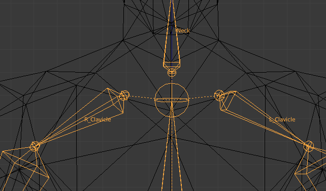
Some bones have associated with them a set of vertices which they influence. "Influence" means that a vertex will move when the bone is moved. For instance, a lower arm bone may influence the vertices in the mesh from the elbow to the wrist. When the lower arm bone rotates (with respect to the upper arm), those vertices rotate with it. The lower arm bone movement will also result in the hand bone and finger bones moving. The vertices influenced by the hand and finger bones will then also move. Vertices comprising the upper arm or other parts of the mesh do not move with the lower arm. As implied above, some frames in the hierarchy may not influence any vertices. They can, perhaps, still be called "bones," but not "influence bones." Those frames still orient their child frames during animation, and TransformationMatrix calculations are still done for every frame in the hierarchy.
The mesh and bone hierarchy in pose position
Bone Influences and Bone Weights
This data is an array specifying which bone influences which vertex, and by how much (by what weighting factor). For each bone, that data is several pairs of numbers: a vertex index and a floating point number between 0 and 1. The vertex index is the position in the mesh vertex array (positions for the mesh in pose position). The weight is "how much" the vertex position will be moved relative to the bone when the bone moves. If several bones influence the same vertex, the sum of the bone weights must equal 1 (one) for proper rendering. E.g., if 2 bones influence a vertex and the bone weight for one of the bones is 0.3, the other bone weight must be 0.7. A bit of code in the final vertex position calculation makes use of that requirement. See below. This data is commonly contained in and maintained by a SkinInfo object. As mentioned above, details of how a SkinInfo object performs its tasks are beyond the scope of this project.
The Animation Process
The discussions above describe the frame hierarchy in "pose" position, ready for animation. The data needed for animating the mesh in real time is normally separate from the hierarchy data. That separation is intentional. A set of animation data represents a single action for the character: running, walking, etc. By separating the animation data from the frame hierarchy, several sets of animation data, each of which can be applied to the "pose" position, can be used to provide changing the action for the character from running to walking, etc., or even apply then simultaneously - e.g., "shoot-while-running."
The animation data is commonly stored with and maintained by an AnimationController object, possibly just a series of application functions. Details of the workings of an Animation Controller are beyond the scope of the project. However, some of the tasks that the AnimationController performs are described below. Animation data for a single character action is called an animation set and is normally comprised of an array of frame animations. The following pseudo-code is arranged to better provide an understanding of the structure and shouldn't be construed as compilable code. An animation set may be organized similar to the following:
struct AnimationSet
{
	string animSetName;

	// for multiple sets, allows selection of actions
	AnimationArray animations;
}

struct Animation
{
	string frameName;

	// look familiar?
	AnimationKeysArray keyFrames;
}

struct AnimationKey
{
	TimeCode keyTime;
	Vector Scale, Translation;
	Quaternion Rotation;
}
Animation Keys
Each frame has associated with it a set of animation "keys." Those keys define the frame's orientation with respect to its parent's orientation (NOT the root frame) at a particular time during the animation sequence. The "time" may be represented as an integer number, a count of clock ticks. (Time may also be a floating point number, representing the time relative to the beginning of the animation).
There are usually a minimum of 2 such "timed" keys, one for the start of the animation (count=0), and one for the end of the animation (count = number of ticks for the entire sequence). In between the start and end counts, there may be keys at various counts during the animation, defining a change in the bone's orientation since the last key (or time within the sequence.) E.g., for a 100 count animation: at count 0, the arm bone is lowered. At count 50, the arm bone is raised. At count 100, the arm bone is lowered back to its original position.
During the animation, the arm starts lowered, raises smoothly to its raised position at count 50, and lowers smoothly to its original position at count 100. Keys are often stored as individual vectors for scale and translation, and quaternions for rotation, to make the process of interpolating keys easier. That is, using the above 100 count animation example, the SRT of the bone at count 25 will be interpolated (calculated) somewhere "between" the key at count 0 and the key at count 50.
If the key is stored as vectors and quaternions, a matrix is calculated from interpolated values for the scale, rotation and translation of the "previous" key and the "next" key (in the example, from the "previous" count 0 key and the "next" count 50 key.) Those interpolated values are commonly calculated as a NLERP (Normalized Linear IntERPolation) or SLERP (Spherical Linear intERPolation) of the quaternions and LERP (Linear intERPolation) of the vectors.
As the rotation change is normally very small between successive ticks, NLERP produces satisfactory results and is faster. If the keys are instead stored as matrices, the key matrices for the "previous" key and "next" key are each decomposed into a quaternion and two vectors. The quaternions are SLERPed, the vectors are LERPed, and a matrix is calculated from the resulting quaternion and vectors. This is not a reliable practice, however, as decomposing a matrix which includes non-uniform scaling may produce erroneous results.
When the matrix for a frame is calculated (for a particular count in the animation sequence), that matrix is stored in that frame's Frame structure as the TranformationMatrix. As mentioned, animation data is stored and maintained separately from the frame hierarchy, so storing each frame matrix in the appropriate place can be done by using the FindFrame() function exampled above. In each render cycle, the AnimationController may perform something like the following:
function CalulateTransformationMatrices( TimeCode deltaTime )
{
    TimeCode keyFrameTime = startTime + deltaTime;
    for each animation in AnimationSet:
    {
        Matrix frameTransform = CalculateFromAnimationKeys( keyFrameTime, animation.frameName );
        Frame frame = FindFrame( rootFrame, animation.frameName );
        frame.TransformationMatrix = frameTransform;
    }
}
Ticks Per Second
The skinned mesh will be animated in real time to present to the user. "Real time" is in seconds, not tick counts. If a 100 count animation (raise and lower an arm) is to take 3 seconds, then ticks-per-second will equal 100 ticks / 3 seconds, or about 33 ticks per second. To start the animation, the tick count is set to 0.
During each render of the scene, the delta-time since the last render (often just a few milliseconds) is multiplied by ticks-per-second, and the tick count is incremented by the value. For an animation that is intended to cycle, e.g., continual waving of the arm, the tick count must be adjusted. That is, as time passes, the tick count will eventually exceed 100.
When that occurs, the tick count is decremented by 100, and the process continues. That is, if the tick count is incremented to 107, the tick count is adjusted to 7, and the animation repeats.
Yet More Matrices Must Be Calculated
Really? REALLY?? Yes, more matrix calcs. The offset matrix discussed above transforms vertices to frame-space, where the TransformationMatrix for that frame can be applied to animate the vertex in frame-space. The task now is to transform the vertex from frame-animated-space to root-frame-animated-space, so it can be rendered.
The process of calculating the transform for frame-animated-space to root-frame-animated-space can be done with a routine very similar to the CalcToRootMatrix function which generates a transform for "pose" frame-space to "pose" root-space. The following calculates a transform for "frame-animated-space" to "root-frame-animated-space."
Rather than building another entire array to hold the root-frame-animated-space transform for each frame, consider: the Frame.TransformationMatrix can just be converted from frame-space to root-space.
// given this function ...
function CalcCombinedMatrix( Frame frame, Matrix parentMatrix )
{
    // transform from frame-space to root-frame-space through the parent's ToRoot matrix
    frame.TransformationMatrix = frame.TransformationMatrix * parentMatrix;

    for each Child in frame:
        CalcCombinedMatrix( Child, frame.TransformationMatrix );
    }

    // ... calculate all the Frame to-root animation matrices
    CalcCombinedMatrix( RootFrame, IdentityMatrix );
Are We There Yet?
Getting really close, but we don't have all the information we need in one place yet. A vertex position can be transformed into frame-pose-space with the Offset matrix. A vertex position can be transformed from frame-animated-space to root-animated-space with the Frame.TransformationMatrix.
For use by the shader (or other rendering routine), we need an array of matrices which will do both of the above operations. However, we need only the matrices for influence bones. So, yet any another array of matrices called FinalMatrix, sized to hold SkinInfo.NumBones(), is created. However, it need be created only once as it can be reused every render cycle. Calculating the final transforms can be done as follows:
// Given a FinalMatrix array..
function CalculateFinalMatrix( int boneIndex )
{
    string boneName = SkinInfo.GetBoneName( boneIndex );
    Frame boneFrame = FindFrame( root_frame, boneName );

    // error check for boneFrame == NULL if desired
    FinalMatrix[ boneIndex ] = OffsetMatrix[ boneIndex ] * boneFrame.TransformationMatrix;
}

// generate all the final matrices
for( int i = 0; i < SkinInfo.NumBones(); i++ )
    CalculateFinalMatrix( i );
How It All Works Together
We're finally ready to actually render the animated skinned mesh! For each render cycle, the following sequence takes place:
1. The animation "time" is incremented. That delta-time is converted to a tick count.
2. For each frame, a timed-key-matrix is calculated from the frame's keys. If the tick count is "between" two keys, the matrix calculated is an interpolation of the key with the next lowest tick count, and the key with the next higher tick count. Those matrices are stored in a key array.
3. When all the frame hierarchy timed-key-matrices have been calculated, the timed-key-matrix for each frame is combined with the timed-key-matrix for its parent.
4. Final transforms are calculated and stored in an array.
5. The next operation is commonly performed in a vertex shader as GPU hardware is more efficient at performing the required calculations, though it can be done in system memory by the application.
The shader is initialized by copying the FinalMatrix array to the GPU, as well as other needed data such as world, view and projection transforms, lighting positions and paramaters, texture data, etc. Each mesh vertex is multiplied by the FinalMatrix of a bone that influences that vertex, then by the bone's weight.
The results of those calculations are summed, resulting in a weight-blended position. If the vertex has an associated normal vector, a similar calculation and summation is done. The weighted-position (see below) is then multiplied by world, view and projection matrices to convert it from root-frame space to world space to homogeneous clip space. As mentioned above, proper rendering requires that the sum of the blend weights (weights for the influence bones) for a vertex sum to 1.
The only way to enforce that assumption is to ensure that the model is created correctly before it is imported into the animation application. However, a simple bit of code can help and reduces by 1 the number of bone weights that must be passed to the vertex position calculations.
Calculating A Weighted Position
// numInfluenceBones is the number of bones which influence the vertex
// Depending on the vertex structure passed to the shader, it may passed in the vertex structure
// or be set as a shader constant
float fLastWeight = 1;
float fWeight; vector vertexPos( 0 );

// start empty
for (int i=0; i < numInfluenceBones-1; i++) // N.B., the last boneweight is not need!
{
	fWeight = boneWeight[ i ];
	vertexPos += inputVertexPos * final_transform[ i ] * fWeight;
	fLastWeight -= fWeight;
}

vertexPos += inputVertexPos * final_transform [ numInfluenceBones - 1 ] * fLastWeight;
Summary
Data for a skinned mesh is loaded into or calculated by an application. That data is comprised of: - mesh vertex data. For each vertex: positions relative to a frame of the bone hierarchy - frame hierarchy data. For each frame: the frame's children, offset matrix, animation key frame data - bone influence data - usually in the form of an array for each bone listing the index and weight for each vertex the bone influences.
Many of the operations described above can be combined into fewer steps and otherwise simplified. The intent of this article is to provide descriptions of the processes involved in animating skinned meshes using matrices, not necessarily in an efficient fashion.
Article Update Log
13 Feb 2014: submitted draft
15 Feb 2014: added weighted vertex position calc code.
15 Feb 2014: submitted for moderator approval
21 Feb 2014: revised tags. Added information regarding mesh "to-root" transform
24 Feb 2014: revised to include more pseudo-code examples and images.
25 Feb 2014: Moderator approval received. Went into peer review stage.
26 Feb 2014: Peer Review complete.
26 Feb 2014: Added NLERP to keyframe interpolation ( credit: member Alundra ).
Other minor edits (spelling).
Corrected description of SkinInfo.GetBoneName( boneIndex ) for "returns index" to "returns name."
Changed "Animation data for a single animation is called an animation set" to "Animation data for a single character action is called an animation set" to avoid confusion (hopefully).
Added "string animSetName;" to AnimationSet structure with comment.
Corrected several misspellings of "quaternion." Other grammar changes.