Introduction
Originally, dynamic shadowing techniques were possible only in a limited way. But with the advent of powerful programmable graphics hardware, dynamic shadow techniques have nearly completely replaced static techniques like light mapping and semi-dynamic techniques like projected shadows. Two popular dynamic shadowing techniques are shadow volumes and shadow mapping.
A closer look
The shadow volumes technique is a geometry based technique that requires the extrusion of the geometry in the direction of the light to generate a closed volume. Then, via ray casting, the shadowed portions of the scene can be determined (usually the stencil buffer is used to simulate ray-casting). This technique is pixel-accurate and doesn't suffer from any aliasing problems, but as with any technique, it suffers from its share of disadvantages. Two major problems with this technique are that it is heavily geometry dependent and fill-rate intensive. Because of this, shadow mapping is slowly becoming more popular.
Shadow mapping on the other hand is an image space technique that involves rendering the scene depth from the light's point of view and using this depth information to determine which portions of the scene in shadow. Though this technique has several advantages, it suffers from aliasing artifacts and z-fighting. But there are solutions to this and since the advantages outweigh the disadvantages, this will be the technique of my choice in this article.
Soft shadows
 Hard shadows destroy the realism of a scene. Hence, we need to fake soft shadows in order to improve the visual quality of the scene. A lot of over-zealous PHD students have come up with papers describing soft shadowing techniques, but in reality, most of these techniques are not viable in real-time, at least when considering complex scenes. Until we have hardware that can overcome some of the limitations of these techniques, we will need to stick to more down-to-earth methods.
In this article, I present an image space method to generate soft-edged shadows using shadow maps. This method doesn't generate perfectly soft shadows (no umbra-penumbra). But it not only solves the aliasing problems of shadow mapping, it improves the visual quality by achieving aesthetically pleasing soft edged shadows.
So how does it work?
First, we generate the shadow map as usual by rendering the scene depth from the light's point of view into a floating point buffer. Then, instead of rendering the scene with shadows, we render the shadowed regions into a screen-sized buffer. Now, we can blur this using a bloom filter and project it back onto the scene in screen space. Sounds simple right?
In this article, we only deal with spot lights, but this technique can easily be extended to handle point lights as well.
Here are the steps:
- Generate the shadow map as usual by writing the scene depth into a floating point buffer.
- Render the shadowed portions of the scene after depth comparison into fixed point texture, without any lighting.
- Blur the above buffer using a bloom filter (though we use a separable Gaussian filter in this article, any filter can be used).
- Project the blurred buffer onto the scene in screen space to get cool soft-edged shadows, along with full lighting.
Step 1: Rendering the shadow map
First, we need to create a texture that can hold the scene depth. Since we need to use this as a render target, we will also need to create a surface that holds the texture's surface data. Thetexture must be a floating point one because of the large range of depth values. The R32F format has sufficient precision and so we use it. Here's the codelet that is used to create the texture.
// Create the shadow map
if( FAILED( g_pd3dDevice->CreateTexture( SHADOW_MAP_SIZE, SHADOW_MAP_SIZE, 1, D3DUSAGE_RENDERTARGET, D3DFMT_R32F, D3DPOOL_DEFAULT, &g_pShadowMap, NULL ) ) )
{
	MessageBox( g_hWnd, "Unable to create shadow map!", "Error", MB_OK | MB_ICONERROR );
	return E_FAIL;
}

// Grab the texture's surface
g_pShadowMap->GetSurfaceLevel( 0, &g_pShadowSurf );
Now, to generate the shadow map, we need to render the scene's depth to the shadow map. To do this, we must render the scene with the light's world-view-projection matrix. Here's how we build that matrix.
// Ordinary view matrix
D3DXMatrixLookAtLH( &matView, &vLightPos, &vLightAim, &g_vUp );

// Projection matrix for the light
D3DXMatrixPerspectiveFovLH( &matProj, D3DXToRadian(30.0f), 1.0f, 1.0f, 1024.0f );

// Concatenate the world matrix with the above two to get the required matrix
matLightViewProj = matWorld * matView * matProj;
Here are vertex and pixel shaders for rendering the scene depth.
// Shadow generation vertex shader
struct VSOUTPUT_SHADOW
{
	float4 vPosition : POSITION;
	float fDepth : TEXCOORD0;
};

VSOUTPUT_SHADOW VS_Shadow( float4 inPosition : POSITION )
{
	// Output struct
	VSOUTPUT_SHADOW OUT = (VSOUTPUT_SHADOW)0;

  	// Output the transformed position
	OUT.vPosition = mul( inPosition, g_matLightViewProj );

  	// Output the scene depth
	OUT.fDepth = OUT.vPosition.z;

  	return OUT;
}
Here, we multiply the position by the light's world-view-projection matrix (g_matLightViewProj) and use the transformed position's z-value as the depth. In the pixel shader, we output the depth ast he color.
float4 PS_Shadow( VSOUTPUT_SHADOW IN ) : COLOR0
{
// Output the scene depth
return float4( IN.fDepth, IN.fDepth, IN.fDepth, 1.0f );
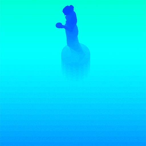
}Voila! We have the shadow map. Below is a color coded version of the shadow map, dark blue indicates smaller depth values, whereas light blue indicates larger depth values.
Step 2: Rendering the shadowed scene into a buffer
Next, we need to render the shadowed portions of the scene to an offscreen buffer so that we can blur it and project it back onto the scene. To do that, we first render the shadowed portions ofthe scene into a screen-sized fixed point texture.
// Create the screen-sized buffer map
if( FAILED( g_pd3dDevice->CreateTexture( SCREEN_WIDTH, SCREEN_HEIGHT, 1, D3DUSAGE_RENDERTARGET, D3DFMT_A8R8G8B8, D3DPOOL_DEFAULT, &g_pScreenMap, NULL ) ) )
{
	MessageBox( g_hWnd, "Unable to create screen map!", "Error", MB_OK | MB_ICONERROR );
	return E_FAIL;
}

// Grab the texture's surface
g_pScreenMap->GetSurfaceLevel( 0, & g_pScreenSurf );
To get the projective texture coordinates, we need a "texture" matrix that will map the position from projection space to texture space.
// Generate the texture matrix
float fTexOffs = 0.5 + (0.5 / (float)SHADOW_MAP_SIZE);

D3DXMATRIX matTexAdj( 0.5f, 0.0f, 0.0f, 0.0f,
					0.0f, -0.5f, 0.0f, 0.0f,
					0.0f, 0.0f, 1.0f, 0.0f,
					fTexOffs, fTexOffs, 0.0f, 1.0f );

matTexture = matLightViewProj * matTexAdj;
We get the shadow factor as usual by depth comparison, but instead of outputting the completely lit scene, we output only the shadow factor. Here are the vertex and pixel shaders that do the job.
// Shadow mapping vertex shader
struct VSOUTPUT_UNLIT
{
    float4 vPosition : POSITION;
    float4 vTexCoord : TEXCOORD0;
    float fDepth : TEXCOORD1;
};

VSOUTPUT_UNLIT VS_Unlit( float4 inPosition : POSITION )
{
    // Output struct
    VSOUTPUT_UNLIT OUT = (VSOUTPUT_UNLIT)0;

    // Output the transformed position
    OUT.vPosition = mul( inPosition, g_matWorldViewProj );

    // Output the projective texture coordinates
    OUT.vTexCoord = mul( inPosition, g_matTexture );

    // Output the scene depth
    OUT.fDepth = mul( inPosition, g_matLightViewProj ).z;

    return OUT;
}
We use percentage closer filtering (PCF) to smoothen out the jagged edges. To "do" PCF, we simply sample the 8 (we're using a 3x3 PCF kernel here) surrounding texels along with the center texeland take the average of all the depth comparisons.
// Shadow mapping pixel shader
float4 PS_Unlit( VSOUTPUT_UNLIT IN ) : COLOR0
{
// Generate the 9 texture co-ordinates for a 3x3 PCF kernel
float4 vTexCoords[9];
// Texel size
float fTexelSize = 1.0f / 1024.0f;
// Generate the tecture co-ordinates for the specified depth-map size
// 4 3 5
// 1 0 2
// 7 6 8
vTexCoords[0] = IN.vTexCoord;
vTexCoords[1] = IN.vTexCoord + float4( -fTexelSize, 0.0f, 0.0f, 0.0f );
vTexCoords[2] = IN.vTexCoord + float4( fTexelSize, 0.0f, 0.0f, 0.0f );
vTexCoords[3] = IN.vTexCoord + float4( 0.0f, -fTexelSize, 0.0f, 0.0f );
vTexCoords[6] = IN.vTexCoord + float4( 0.0f, fTexelSize, 0.0f, 0.0f );
vTexCoords[4] = IN.vTexCoord + float4( -fTexelSize, -fTexelSize, 0.0f, 0.0f );
vTexCoords[5] = IN.vTexCoord + float4( fTexelSize, -fTexelSize, 0.0f, 0.0f );
vTexCoords[7] = IN.vTexCoord + float4( -fTexelSize, fTexelSize, 0.0f, 0.0f );
vTexCoords[8] = IN.vTexCoord + float4( fTexelSize, fTexelSize, 0.0f, 0.0f );
// Sample each of them checking whether the pixel under test is shadowed or not
float fShadowTerms[9];
float fShadowTerm = 0.0f;
for( int i = 0; i < 9; i++ )
{
float A = tex2Dproj( ShadowSampler, vTexCoords ).r;
float B = (IN.fDepth - 0.1f);
// Texel is shadowed
fShadowTerms = A < B ? 0.0f : 1.0f;
fShadowTerm += fShadowTerms;
}
// Get the average
fShadowTerm /= 9.0f;
return fShadowTerm;
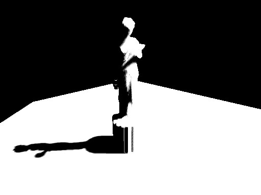
}The screen buffer is good to go! Now all we need to do is blur this and project it back onto the scene in screen space.
Step 3: Blurring the screen buffer
We use a separable Gaussian filter to blur the screen buffer, but one could also use a Poisson filter. The render targets this time are A8R8G8B8 textures accompanied by corresponding surfaces. We need 2 render targets, one for the horizontal pass and the other for the vertical pass.
// Create the blur maps
for( int i = 0; i < 2; i++ )
{
    if( FAILED( g_pd3dDevice->CreateTexture( SCREEN_WIDTH, SCREEN_HEIGHT, 1, D3DUSAGE_RENDERTARGET, D3DFMT_A8R8G8B8, D3DPOOL_DEFAULT, &g_pBlurMap, NULL ) ) )
    {
        MessageBox( g_hWnd, "Unable to create blur map!", "Error", MB_OK | MB_ICONERROR );
        return E_FAIL;
    }

    // Grab the texture's surface
    g_pBlurMap->GetSurfaceLevel( 0, & g_pBlurSurf );
}
We generate 15 Gaussian offsets and their corresponding weights using the following functions.
float GetGaussianDistribution( float x, float y, float rho )
{
    float g = 1.0f / sqrt( 2.0f * 3.141592654f * rho * rho );
    return g * exp( -(x * x + y * y) / (2 * rho * rho) );
}

void GetGaussianOffsets( bool bHorizontal, D3DXVECTOR2 vViewportTexelSize, D3DXVECTOR2* vSampleOffsets, float* fSampleWeights )
{
    // Get the center texel offset and weight
    fSampleWeights[0] = 1.0f * GetGaussianDistribution( 0, 0, 2.0f );
    vSampleOffsets[0] = D3DXVECTOR2( 0.0f, 0.0f );

    // Get the offsets and weights for the remaining taps
    if( bHorizontal )
    {
        for( int i = 1; i < 15; i += 2 )
        {
        	vSampleOffsets[i + 0] = D3DXVECTOR2( i * vViewportTexelSize.x, 0.0f );
        	vSampleOffsets[i + 1] = D3DXVECTOR2( -i * vViewportTexelSize.x, 0.0f );
        	fSampleWeights[i + 0] = 2.0f * GetGaussianDistribution( float(i + 0), 0.0f, 3.0f );
        	fSampleWeights[i + 1] = 2.0f * GetGaussianDistribution( float(i + 1), 0.0f, 3.0f );
        }
    }
	else
	{
		for( int i = 1; i < 15; i += 2 )
		{
            vSampleOffsets[i + 0] = D3DXVECTOR2( 0.0f, i * vViewportTexelSize.y );
            vSampleOffsets[i + 1] = D3DXVECTOR2( 0.0f, -i * vViewportTexelSize.y );
            fSampleWeights[i + 0] = 2.0f * GetGaussianDistribution( 0.0f, float(i + 0), 3.0f );
            fSampleWeights[i + 1] = 2.0f * GetGaussianDistribution( 0.0f, float(i + 1), 3.0f );
        }
	}
}
To blur the screen buffer, we set the blur map as the render target and render a screen sized quad with the following vertex and pixel shaders.
// Gaussian filter vertex shader
struct VSOUTPUT_BLUR
{
    float4 vPosition : POSITION;
    float2 vTexCoord : TEXCOORD0;
};

VSOUTPUT_BLUR VS_Blur( float4 inPosition : POSITION, float2 inTexCoord : TEXCOORD0 )
{
    // Output struct
    VSOUTPUT_BLUR OUT = (VSOUTPUT_BLUR)0;
    // Output the position
    OUT.vPosition = inPosition;
    // Output the texture coordinates
    OUT.vTexCoord = inTexCoord;
    return OUT;
}

// Horizontal blur pixel shader
float4 PS_BlurH( VSOUTPUT_BLUR IN ): COLOR0
{
    // Accumulated color
    float4 vAccum = float4( 0.0f, 0.0f, 0.0f, 0.0f );

    // Sample the taps (g_vSampleOffsets holds the texel offsets
    // and g_fSampleWeights holds the texel weights)
    for(int i = 0; i < 15; i++ )
    {
    	vAccum += tex2D( ScreenSampler, IN.vTexCoord + g_vSampleOffsets ) * g_fSampleWeights;
    }

    return vAccum;
}

// Vertical blur pixel shader
float4 PS_BlurV( VSOUTPUT_BLUR IN ): COLOR0
{
    // Accumulated color
    float4 vAccum = float4( 0.0f, 0.0f, 0.0f, 0.0f );

    // Sample the taps (g_vSampleOffsets holds the texel offsets and
    // g_fSampleWeights holds the texel weights)
    for( int i = 0; i < 15; i++ )
    {
    	vAccum += tex2D( BlurHSampler, IN.vTexCoord + g_vSampleOffsets ) * g_fSampleWeights;
    }

	return vAccum;
}
There, the blur maps are ready. To increase the blurriness of the shadows, increase the texel sampling distance. The last step, of course, is to project the blurred map back onto the scene inscreen space.
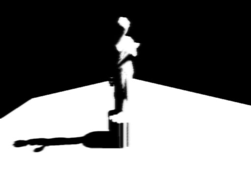
After first Gaussian pass)
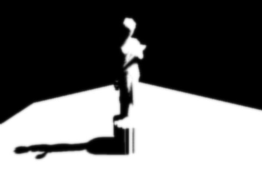
After second Gaussian pass
Step 4: Rendering the shadowed scene
To project the blur map onto the scene, we render the scene as usual, but project the blur map using screen-space coordinates. We use the clip space position with some hard-coded math to generatethe screen-space coordinates. The vertex and pixel shaders shown below render the scene with per-pixel lighting along with shadows.
struct VSOUTPUT_SCENE
{
    float4 vPosition : POSITION;
    float2 vTexCoord : TEXCOORD0;
    float4 vProjCoord : TEXCOORD1;
    float4 vScreenCoord : TEXCOORD2;
    float3 vNormal : TEXCOORD3;
    float3 vLightVec : TEXCOORD4;
    float3 vEyeVec : TEXCOORD5;
};

// Scene vertex shader
VSOUTPUT_SCENE VS_Scene( float4 inPosition : POSITION, float3 inNormal : NORMAL, float2 inTexCoord : TEXCOORD0 )
{
	VSOUTPUT_SCENE OUT = (VSOUTPUT_SCENE)0;

  	// Output the transformed position
	OUT.vPosition = mul( inPosition, g_matWorldViewProj );

  	// Output the texture coordinates
	OUT.vTexCoord = inTexCoord;

  	// Output the projective texture coordinates
	// (we use this to project the spot texture down onto the scene)
	OUT.vProjCoord = mul( inPosition, g_matTexture );

  	// Output the screen-space texture coordinates
    OUT.vScreenCoord.x = ( OUT.vPosition.x * 0.5 + OUT.vPosition.w * 0.5 );
    OUT.vScreenCoord.y = ( OUT.vPosition.w * 0.5 - OUT.vPosition.y * 0.5 );
    OUT.vScreenCoord.z = OUT.vPosition.w;
    OUT.vScreenCoord.w = OUT.vPosition.w;

  	// Get the world space vertex position
	float4 vWorldPos = mul( inPosition, g_matWorld );

  	// Output the world space normal
	OUT.vNormal = mul( inNormal, g_matWorldIT );

  	// Move the light vector into tangent space
	OUT.vLightVec = g_vLightPos.xyz - vWorldPos.xyz;

  	// Move the eye vector into tangent space
	OUT.vEyeVec = g_vEyePos.xyz - vWorldPos.xyz;

  	return OUT;
}
We add an additional spot term by projecting down a spot texture from the light. This not only simulates a spot lighting effect, it also cuts out parts of the scene outside the shadow map. Thespot map is projected down using standard projective texturing.
float4 PS_Scene( VSOUTPUT_SCENE IN ) : COLOR0
{
// Normalize the normal, light and eye vectors
IN.vNormal = normalize( IN.vNormal );
IN.vLightVec = normalize( IN.vLightVec );
IN.vEyeVec = normalize( IN.vEyeVec );
// Sample the color and normal maps
float4 vColor = tex2D( ColorSampler, IN.vTexCoord );
// Compute the ambient, diffuse and specular lighting terms
float ambient = 0.0f;
float diffuse = max( dot( IN.vNormal, IN.vLightVec ), 0 );
float specular = pow(max(dot( 2 * dot( IN.vNormal, IN.vLightVec ) * IN.vNormal - IN.vLightVec, IN.vEyeVec ), 0 ), 8 );
if( diffuse == 0 ) specular = 0;
// Grab the shadow term
float fShadowTerm = tex2Dproj( BlurVSampler, IN.vScreenCoord );
// Grab the spot term
float fSpotTerm = tex2Dproj( SpotSampler, IN.vProjCoord );
// Compute the final color
return (ambient * vColor) +
(diffuse * vColor * g_vLightColor * fShadowTerm * fSpotTerm) +
(specular * vColor * g_vLightColor.a * fShadowTerm * fSpotTerm);
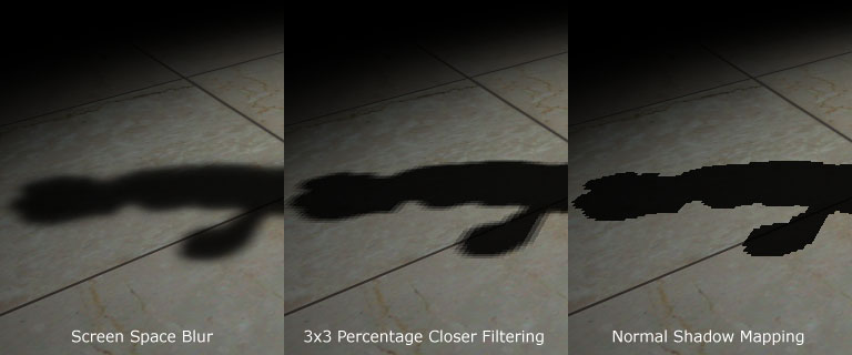
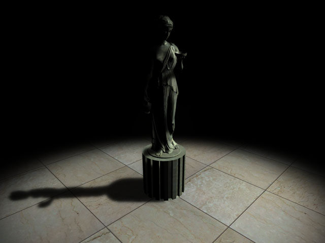
}That's it! We have soft edged shadows that look quite nice! The advantage of this technique is that it completely removes edge-aliasing artifacts that the shadow mapping technique suffers from.Another advantage is that one can generate soft shadows for multiple lights with a small memory overhead. When dealing with multiple lights, all you need is one shadow map per light, whereas thescreen and blur buffers can be common to all the lights! Finally, this technique can be applied to both shadow maps and shadow volumes, so irrespective of the shadowing technique, you can generatesoft-edged shadows with this method. One disadvantage is that this method is a wee bit fill-rate intensive due to the Gaussian filter. This can be minimized by using smaller blur buffers and slightlysacrificing the visual quality.
Here's a comparison between the approach mentioned here, 3x3 percentage closer filtering and normal shadow mapping.
Thank you for reading my article. I hope you liked it. If you have any doubts, questions or comments, please feel free to mail me at anidex@yahoo.com.
References
- Hardware Shadow Mapping. Cass Everitt, Ashu Rege and Cem Cebenoyan.
- Hardware-accelerated Rendering of Antialiased Shadows with Shadow Maps. Stefan Brabec and Hans-Peter Seidel.


Now I'll have to try and implement that by myself, we'll see how it goes.