Shadows used to be just a patch of darkened texture, usually round in shape, which is projected onto the floor below characters or objects in a game. One must be ill informed or na?ve to think that we can still get away with this kind of sloppy "hacks" in future 3D games. There used to be a time where shadows are just too expensive to be rendered properly in real-time, but with the ever-increasing power of graphics hardware, failure to provide proper shadows no longer meant mediocre implementations, it borders on being guilty of criminally under-utilizing the graphics hardware available.
There are many differing shadowing techniques and approaches to implementing shadows and nailing down a "best" solution is difficult. In order to understand all the approaches and appreciate their differences, strengths and weakness, I strongly suggest reading anything and everything about doing shadows in 3D. We should not constrain ourselves to just studying shadow volume technique; any shadowing technique is worth a look. Chapter 6 of [13] has a wonderful high-level discussion on most of the known shadowing techniques. To limit the scope of this paper, we shall only discuss the theory and implementation issues of stencil shadow volumes with particular reference to using Microsoft's Direct3D API. It would also be good to understand that stencil shadow volume just isn't the "end all" shadowing technique. A discussion on the strengths of differing shadowing technique can be found at [4] with reference to a game setting. Just recently, Eric Lengyel [11] also presented a very complete article on implementing shadow volumes in OpenGL at the Gamasutra website [17]. The mathematical derivations of Lengyel's article can be found in [12]. Going back a few years, there was the famous "Carmack On Shadow Volumes" text file [6], which is nothing more that an email from John Carmack of id Software to Mark Kilgard of Nvidia about the derivation of the depth-fail shadow volume implementation. It's interesting to note that Carmack independently discovered the depth-fail method while Bill Bilodeau and Mike Songy [7] had also presented similar approach to shadow volumes. Consequently, the depth-fail method is now commonly known as "Carmack's Reverse".
[size="5"]Stencil Shadow Volume Concept
Frank Crow [8] first presented the idea of using shadow volumes for shadow casting in 1977. Tim Heidmann [5] of Silicon Graphics implemented Crow's shadow volume by cunningly utilizing the stencil buffer for shadow volume counting in IRIX GL. Lets take a look at how the original stencil shadow volume technique works.
Figure 1: Occluder and shadow volume
As common convention goes, any objects in a scene that cast shadows are called occluders. As shown in Figure 1 above, we have a simplistic 2D view (top down) of a scene with a sphere as the occluder. The rectangle to the right of the sphere is the shadow receiver. For simplicity, we do not take into account the shadow volume created by the rectangle. The shaded region represents the shadow volume, in 2D, created by the occluder. The shadow volume is the result of extruding the silhouette edges from the point-of-view of the light source to a finite or infinite distance.
Figure 2: Silhouette of occluders
Figure 2 shows the probable silhouette of the sphere generated from the viewing position of the light source. The silhouette is simply made up of edges that consist of two vertices each. These edges are then extruded in the direction as shown by the broken arrows originating from the light source. By extruding the silhouette edges, we are effectively creating the shadow volume. It should be noted at this point in time that shadow volume extrusion differs for different light sources. For point light sources, the silhouette edges extrude exactly point for point. For infinite directional light sources, the silhouette edges extrude to a single point. We will go into the details of determining silhouette edges and the creation of the shadow volumes later. The magnitude of the extrusion can be either finite or infinite. Thus, implementations that extrude silhouette edges to infinity are commonly known as Infinite Shadow Volumes.
Figure 3: Depth-Pass stencil operation
Figure 3 shows the numerous possible viewing direction of a player in the scene. The numbers at the end of the arrows are the values left in the stencil buffer after rendering the shadow volume. Fragments with non-zero stencil values are considered to be in shadow. The generation of the values in the stencil buffer is the result of the following stencil operations:
- Render front face of shadow volume. If depth test passes, increment stencil value, else does nothing. Disable draw to frame and depth buffer.
- Render back face of shadow volume. If depth test passes, decrement stencil value, else does nothing. Disable draw to frame and depth buffer.
Let's assume that we had already rendered the objects onto the frame buffer prior to the above stenciling operations. This means that the depth buffer would have been set with the correct values for depth testing or z-testing if you like. The 2 leftmost ray originating from the eye position does not hit any part of the shadow volume (in gray), hence the resultant stencil values is 0, which means that the fragment represented by this two rays are not in shadow. Now lets trace the 3[sup]rd[/sup] ray from the left. When we render the front face of the shadow volume, the depth test would pass and the stencil value would be incremented to 1. When we render the back face of the shadow volume, the depth test would fail since the back face of the shadow volume is behind the occluder. Thus the stencil value for the fragment represented by this ray remains at 1. This means that the fragment is in shadow since its stencil value is non-zero.
Does the shadow volume counting work for multiple shadow volumes? Yes it does.
Figure 4: Multiple shadow volumes counting
Figure 4 above shows that the counting using the stencil buffer will still work even for multiple intersecting shadow volumes.
[size="5"]Finite Volume vs Infinite Volume
Referring back to Figure 1, you could see that the shadow volume is supposed to extrude to infinity. This is actually not strictly a requirement. We send the shadow volume to infinity in order to avoid the awkward situation whereby the light source is very close to an occluder.
Figure 5: Finite shadow volume fails to shadow other objects
With the light close to object A, a finite shadow volume may not be enough to reach object B. The ray from the eye towards object B will end up with a fragment stencil value of 0 when in fact it should have been non-zero! An infinite shadow volume would ensure that no matter how close the object is to an occluder, the resultant shadow volume would cover all the objects in the scene. We will discuss how to extrude vertices to infinity shortly.
[size="5"]Carmack's Reverse
Why did John Carmack, Bill Bilodeau and Mike Songy even bother to crack their heads to come out with an alternative stencil algorithm since the depth-pass technique seems to work great? Depth-pass really works well, at least most of the time. But when the eye point enters the shadow volume, all hell break loose.

Figure 6: When eye point is within the shadow volume, depth-pass stencil operation fails
As shown in Figure 6 above, the depth-pass technique utterly fails when the eye point is within the shadow volume. This meant that we could not have that big bad horned reaper sneaking up from behind you while engulfing you in the enlarging darkness of his shadows. John Carmack would never have it this way! The following is the depth-fail (a.k.a Carmack's Reverse) algorithm:
- Render back face of shadow volume. If depth test fails, increment stencil value, else does nothing. Disable draw to frame and depth buffer.
- Render front face of shadow volume. If depth test fails, decrement stencil value, else does nothing. Disable draw to frame and depth buffer.
Figure 7: Depth-fail works even if eye point is in shadow
Depth-fail is also commonly referred to as z-fail. Figure 7 shows the depth-fail technique working even when the eye point is in shadow. If you think about the scenario where the eye position is outside the shadow volume, the depth-fail technique should work as well. But really, it fails in some cases. We shall discuss these scenarios soon; just remember for now that both the depth-pass and depth-fail techniques are not perfect. In fact, we would need a combination of different methods to come up with a robust solution for shadow volumes. [11] and [10] contains some very good discussion on robust stencil shadow volume solutions.
[size="5"]Capping For Depth-Fail
To put in non-zero values into the stencil buffer, the depth-fail technique depends on the failure to render the shadow volume's back faces with respect to the eye position. This meant that the shadow volume must be a closed volume; the shadow volume must be capped at both the front and back end (even if back end is at infinity). Without capping, the depth-fail technique would produce erroneous results. Amazing as it may sound, but yes, you can cap the shadow volume even at infinity.
Figure 8: Capping for shadow volume
As shown in Figure 8, the front and back cap (bold lines) creates a closed shadow volume. Both the front and back caps are considered back face from the two eye positions. With depth-fail stenciling operations, the capping will create correct non-zero stencil values. There are a few ways to create the front and back capping. Mark Kilgard [2] described a non-trivial method of creating the front cap. The method basically involves the projection of the occluder's back facing geometries onto the near clip plane and uses these geometries as the front cap. Alternatively, we can build the front cap by reusing the front facing triangles with respect to the light source. The geometries used in the front cap can then be extruded, with their ordering reversed, to create the back cap. Reversing the ordering is to ensure that the back cap face outward from the shadow volume. In fact, we must always ensure that the primitives, in our case triangles, that define the entire shadow volume are outward facing as shown in Figure 9. It must be noted that rendering closed shadow volumes are somewhat more expensive than using depth-pass without shadow volume capping. Besides a larger primitive count for the shadow volume, additional computational resource are also needed to compute the front and back capping. We will go into the details of capping shadow volumes shortly.
Figure 9: Shadow volume must be outward facing
[size="5"]Putting It Together
Let's collate what we have learned and try to come up with all the require steps to do stencil shadow volumes before we tackle all the deficiencies of the techniques discussed. A general list of steps to implement stencil shadow volumes would be:
- Render all the objects using only ambient lighting and any other surface-shading attribute. Rendering should not depend on any particular light source. Make sure depth buffer is written.
- Starting with a light source, clear the stencil buffer and calculate the silhouette of all the occluders with respect to the light source.
- Extrude the silhouette away from the light source to a finite or infinite distance to form the shadow volumes and generate the capping if depth-fail technique was used. (Infinite shadow volume extrusion is not really compulsory)
- Render the shadow volumes using the selected technique. Depth-pass or depth-fail.
- Using the updated stencil buffer, do a lighting pass to shade (make it a tone darker) the fragments that corresponds to non-zero stencil values.
- Repeat step 2 to 5 for all the lights in the scene.
From the released screen shots of the upcoming Doom3 engine, I estimate that id Software would have to limit the number of shadow casting lights in any scene to a maximum of say 4 or 5. Well, we will know when Doom3 hits the shelves next year.
[size="5"]Silhouette Determination
The very first step to constructing a shadow volume is to determine the silhouette of the occluder. The stencil shadow algorithm requires that the occluders be closed triangle meshes. This meant that every edge in the model must only be shared by 2 triangles thus disallowing any holes that would expose the interior of the model. We are only interested in the edges shared by a triangle that faces the light source and another triangle that face away from the light source. There are many ways to calculate the silhouette edges and every single one of these methods are CPU cycles hungry. Lets assume we are working with an indexed triangle mesh.
Figure 10: Edge elimination for silhouette determination
Figure 10 shows one side of a box that is made up of four triangles with a consistent counter-clockwise winding. The broken lines indicate the redundant internal edges since we are only interested in the solid line that forms the outline of the box. The redundant internal edges are indexed twice as they are shared by two triangles. We take advantage of this property to come up with a simple method to determine the silhouette edges.
- Loop through all the model's triangles
- If triangle faces the light source (dot product > 0)
- Insert the three edges (pair of vertices), into an edge stack
- Check for previous occurrence of each edges or it's reverse in the stack
- If an edge or its reverse is found in the stack, remove both edges
- Start with new triangle
Eric Lengyel [11] presented another silhouette determination algorithm that makes use of the consistent winding (counterclockwise) of vertices. The method requires 2 passes on all the triangles of the model to filter in all the edges shared by pairs of triangles. The resultant edges list then undergo the dot product operations to get the edges that are shared by a light facing triangle and a non light facing triangle.
It is important to note that silhouette determination is one of the two most expensive operations in stencil shadow volume implementation. The other is the shadow volume rendering passes to update the stencil buffer. These two areas are prime candidates for aggressive optimizations, which we will discuss in detail at the concluding sections of this paper.
[size="5"]Generating Shadow Volume Capping
Remember that shadow volume capping is only necessary for the depth-fail technique. The purpose of doing shadow volume capping is to ensure that our shadow volume is closed, and it must be closed even at infinity. Interestingly, the extrusion of geometries for point light sources and infinite directional light sources are different. Point light sources would extrude the silhouette edges exactly point for point while infinite directional light sources would extrude all silhouette edges to a single point at infinity. This would meant that the shadow volume's back capping would be redundant for infinite directional light sources as it is already closed.
The ideal time to generate the front and back capping would be during the silhouette generation since we are already generating the angles between the light vector and the edges. For the front cap, we just need to duplicate all front facing geometries and use these geometries for extrusion to form the back capping as well. Note that the back cap is only necessary for point light sources.
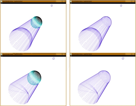
Figure 11: Closed shadow volume with point light source
Figure 11 shows two sets of images employing different geometries to close the shadow volume. The first row depicts a closed shadow volume formed by a front and back capping reusing light facing geometries. The second row shows a closed shadow volume with a front cap that reuses light facing geometries of the occluder and a triangle-fan back cap constructed from extruded silhouette edges. The triangle-fan back cap should be used as it results in less geometry and hence requires less memory and rendering time. When reusing the front facing geometries of the occluder, we should be extremely careful with regards to rendering the shadow volume since the shadow volume's front capping geometries are physically coplanar with the occluder's front facing geometries. Most often than not, precision problems will cause the front capping geometries of the shadow volume to be rendered in front of the occluder's front facing geometries causing the entire occluder to be engulfed in its own shadow volume. We can make use of the [font="Courier New"][color="#000080"]D3DRS_ZBIAS[/color][/font] flag in Direct3D's [font="Courier New"][color="#000080"]D3DRENDERSTATETYPE[/color][/font] to force the occluder's front facing geometries to be rendered in front of its shadow volume front cap. Simply use the [font="Courier New"][color="#000080"]D3DRS_ZBIAS[/color][/font] flag when setting the render state (e.g. [font="Courier New"][color="#000080"]pd3dDevice->SetRenderState(D3DRS_ZBIAS, value)[/color][/font]). We set the flag value to a higher value for the occluder's geometries and a lower value for its shadow volume. This will ensure that the front cap of the shadow volume is rendered behind the occluder's front facing geometries.
[size="5"]Extruding Geometries To Infinity
As discussed previously, we need to extrude the silhouette edges to infinity to avoid the situation shown in Figure 5 where a finite shadow volume extrusion fails to cover all the shadow receivers in a scene. However, it is not compulsory to extrude the silhouette edges to infinity if we can ensure that the situation in Figure 5 never happens in our scene. In practical cases, a large value would normally be more than adequate.
Mark Kilgard [2] introduced the trick of using the w value of homogenous coordinates to render semi-infinite vertices. In 4D homogenous coordinates, we represent a point or vector as (x, y, z, w) with w being the 4[sup]th[/sup] coordinate. For points, w is equal to 1.0. For vectors, w is equal to 0.0. The homogeneous notation is extremely useful for transforming both points and vectors. Since translation is only meaningful to points and not vectors, the value of w plays an important role in transforming only points and not vertices. This can be easily deduced since the translation values of a transformation matrix are on either the 4[sup]th[/sup] column or the 4[sup]th[/sup] row depending on the matrix convention. By setting the w value of the infinity-bound vertices to 0.0, we change the homogenous representation from that of a 3D point to a 3D vector. The rendering of a vector (w = 0.0) in clip space would be semi-infinite. It is important to note that we should only set the w values to 0.0 after transformation to clip space. In Direct3D, this would mean the combined transformation of the world, view and projection matrices. This is because when we set the flexible vertex format to [font="Courier New"][color="#000080"]D3DFVF_XYZRHW[/color][/font], we are bypassing Direct3D's transformation and lighting pipeline. Direct3D assumes that we had already transformed and lit the vertices. Ideally, the extrusion of geometries should be done in a vertex program since we are already working in clip space in a vertex shader. In fact, vertex shaders and stencil shadow volumes is a match made in heaven. We will discuss the benefits of doing shadow volumes in a vertex program at the end of this paper.
While extruding geometries by a huge distance or to infinity helps to avoid the problem of finite shadow volume cover, it also generates another problem. Imagine two players in a dungeon First-Person-Shooter (FPS) game, roaming in adjacent rooms separated by a solid brick wall. The table lamp in one of the room causes one of the players to cast a shadow onto the brick separating the rooms. The player on the other room would see the shadow cast by the table lamp since the shadow volume extrudes out to infinity. The solid brick wall suddenly becomes like a thin piece of paper with a "ghost" shadow on it. Luckily, we can avoid this kind of situation in the very first place by culling away the shadow casting player's avatars using occlusion-culling techniques. Figure 12 shows a more awkward situation whereby the camera sees both the occluder and the occluder's ghost shadow on the other side of the terrain. This scenario is very possible especially for flight simulations or aerial combat games. The only possible solution to avoid both the finite shadow volume cover (Figure 5) and ghost shadow (Figure 12) is to impose limitations on the placing of light sources and occluders in a scene. If we can be sure that an occluder can never get closer than a certain distance of a shadow casting light source, then we can safely estimate the largest distance we would need to extrude the shadow volume in order to provide adequate shadow cover while not causing ghost shadows.
Figure 12: Ghost shadow effect due to large extrusion distance
[size="5"]View Frustum Clipping - The Ultimate Evil
It is time to confront the greatest evil in stencil shadow volumes: View frustum clipping. Clipping is a potential problem to any 3D rendering technique because we rely on a perspective projection view of our 3D worlds. The view frustum requires a near clipping distance and a far clipping distance, for the creation of a near clip plane and a far clip plane. Both the depth-pass and depth-fail techniques suffer from view frustum clipping problem. Depth-pass technique suffers from errors when the shadow volume gets clipped after intersecting the near clip plane as shown in Figure 13. The red arrow represents one case whereby the stencil values for the associated fragment will be wrong due to the clipping of the shadow volume's front face.
Figure 13: Shadow volume clipped at near clip plane causing depth-pass errors
On the other hand, depth-fail technique suffers from errors arising due to the clipping of the shadow volume with the far clip plane. Since the far clip plane is at a finite distance from the eye position, the depth-fail technique will almost certainly produce the wrong result when the shadow volume gets clipped at the far plane. The red arrow in Figure 14 represents a case whereby the depth-fail technique will generate errors since the back face of the shadow volume had been clipped at the far plane.
Figure 14: Shadow volume clipped at far clip plane causing depth-fail errors
We can solve the clipping problems by adjusting the clipping planes, but it is not always advisable to do so. For example, moving the near clip plane will greatly affect the depth precision and may have negative impacts on other operations that uses the depth buffer.
Mark Kilgard [2] presented an interesting idea of handling the two possible scenarios when shadow volumes intersect the near clip plane. The idea was to "cap" the shadow volume at the near clip plane, so that the previously clipped front facing geometries can now be rendered at the near clip plane. The first scenario is when all the vertices of the occluder's silhouette projects to the near clip plane. In this case, a quad strip loop is generated from all front facing vertices within the silhouette of the occluder. The quad strip loop is then projected onto the near clip plane thus forming a capping for the shadow volume.
The second scenario occurs when only part of the shadow volume projects onto the near clip plane. This proves to be very much more difficult to handle than the previous scenario. To his credit, Kilgard devised an elaborate system to filter out the vertices of triangles (facing away from the light) that should be projected onto the near clip plane in order to cap the shadow volume. The capping of shadow volumes at the near clip plane gave rise to another problem: depth precision. Rendering geometries at the near clip plane is analogous to rolling a coin along a razor's edge; the coin can drop down both sides easily. What this means is that the near plane may still clip the vertices that were meant to cap the shadow volume. To overcome this, Kilgard devised yet another method that builds a depth range "ledge" from the eye point to the near plane. The idea is to render the shadow volume from a depth range of 0.0 to 1.0, while normal scene rendering occurs within a depth range of 0.1 to 1.0. The ledge could be build into the view frustum by manipulating the perspective projection matrix. Once in place, the near clip plane capping of shadow volumes is done at a depth value of 0.05, which is half of the ledge. This idea is indeed original but it does not solve the problem totally. Cracks or "holes" in the near plane shadow cap occurs very frequently resulting in erroneous results. The conclusion with the near clip plane problem is that there are really no trivial solutions. At least, there is no known foolproof solution to the problem at the time of this writing. This makes the depth-pass technique very undesirable.
Fortunately, there is an elegant solution to the far plane clipping problem that plagues the depth-fail technique. The antidote to the problem is simply to use an infinite perspective view projection or simply an infinite view frustum. By projecting a far plane all the way to infinity, there is no mathematical chance of the shadow volume being clipped by the far plane when we are rendering the shadow volume. Even if the shadow volume were extruded to infinity, the far plane at infinity would still not clip it! Eric Lengyel presented the mathematic derivation for OpenGL perspective projection matrix in [11]. We are going to deal with Direct3D perspective projection matrix here. Lets start by looking at a standard left-handed perspective projection matrix in Direct3D:
(1)
Variables:
n: near plane distance
f: far plane distance
fov[sub]w[/sub]: horizontal field of view in radians
fov[sub]h[/sub]: vertical field of view in radians
A far plane at infinity means that the far plane distance needs to approach ?. Hence, we get the following perspective projection matrix when the far plane distance goes towards the infinity limit:
(2)
Equation (2) defines a perspective projection view that extends from the near plane to a far plane at infinity. But, are we absolutely sure that the vertices that we extruded to infinity using the 4D homogeneous vector does not get clipped at infinity? Sadly, we cannot be 100% sure of this due to limited hardware precision. In reality, graphics hardware sometimes produces points with a normalized z-coordinate marginally greater than 1. These values are then converted into integers for use in the depth buffer. This is going to weak havoc since our stencil operations depends wholly on the depth value testing. Fortunately, there is workaround for this problem. The solution is to map the z-coordinate values of our normalized device coordinates from a range of [0, 1] to [0, 1-e], where e is a small positive constant. What this means is that we are trying to map the z coordinate of a point at infinity to a value that is slightly less than 1.0 in normalized device coordinates. Let D[sub]z---[/sub] be the original z-coordinate value and D?[sub]z--[/sub] be the mapped z-coordinate. The mapping can be achieved using equation (3) shown below:

(3)
Now, let's make use of equation (2) to transform a point A from camera space (A[sub]cam[/sub]) to clip space (A[sub]clip[/sub]). Note that camera space is also commonly referred to as eye space.
Which would gives us:
(4)
Let's factor the desired range mapping into equation (3) by replacing D[sub]z---[/sub] with
 and D?[sub]z--[/sub] with
  :
:
(5)
Simplifying equation (5) by using the values given by equation (4), we get:
(6)
Using equation (6), we can enforce our range mapping into the projection matrix P[sub]?[/sub] given by equation (2) to get the following:
(7)
Thus, we can use the perspective projection matrix given in equation (7) without fear of far plane clipping of shadow volumes occurring at infinity! You might wonder whether stretching the view frustum volume all the way to infinity would impact the depth buffer precision. The answer is, yes it does affect precision, but the loss of precision is really negligible. The amount of numerical range lost when extending the far plane out to infinity is only
 . Say our original near clip plane is at 0.1 meter and far clip plane is at 100 meters. This range corresponds to a depth range of [-1.0, 1.0]. We then extend the far plane distance to infinity. The range from 0.1 meter to 100 meters would now correspond to a depth range of [-1, 0.999]. The range from 100 meters to infinity would correspond to a depth range of [0.999, 1.0]. The loss in depth buffer precision is really not a big impact at all. The larger the difference between the n and f values, the smaller the loss in depth buffer precision. You can find the above derivations and many other related mathematical derivations in Eric Lengyel's book [12]. It should be noted that using an infinite view frustum meant that we have to draw more geometries. This may pose a potential performance problem.
The infinite view frustum projection is really just a software solution to the far plane clipping problem. Mark Kilgard and Cass Everitt [10] presented a hardware solution to the problem instead of using an infinite view frustum. Newer graphics hardware now supports a technique called "depth-clamping". In fact, the depth-clamping extension, [font="Courier New"][color="#000080"]NV_depth_clamp[/color][/font], was specifically added to Nvidia's GeForce3 and above graphics cards to solve the far plane clipping problem for shadow volumes. When active, depth-clamping would force all the objects beyond the far clip plane to be drawn at the far clip plane with the maximum depth value. This meant that we can project the closed shadow volume to any arbitrary distance without fear of it being clipped by the far plane as the hardware will handle the drawing properly. With such automatic support from graphics hardware, depth-fail shadow volumes become very easy to implement. We can extend the shadow volume to infinity while rendering with our finite view frustum and still get correct depth-fail stencil values! Well, the tradeoff is hardware dependence. If we want the depth-fail shadow volume to work for any graphics card (with stenciling support), we will have to use the infinite view frustum projection instead of the depth-clamping extension.
[size="5"]Depth-Pass or Depth-Fail
We had run through most of the method and implementation issues of both the depth-pass and depth-fail techniques for doing stencil shadow volumes. So which method should we use in our games? Lets take stock of the pros and cons of both techniques.
[size="3"]Depth-pass
- Advantages
- Does not require capping for shadow volumes
- Less geometry to render
- Faster of the two techniques
- Easier to implement if we ignore the near plane clipping problem
- Does not require an infinite perspective projection
- Not robust due to unsolvable near plane clipping problem
- Advantages
- Robust solution since far plane clipping problem can be solved elegantly
- Requires capping to form closed shadow volumes
More geometry to render due to capping
- Slower of the two techniques
- Slightly more difficult to implement
- Requires an infinite perspective projection
On the whole, it is beneficial to combine other techniques with shadow volumes to achieve better quality shadows. One example of such hybrid implementation is the Power Render X [16] game engine that generates shadows using shadow volumes and then fade out the shadows with respect to distance from the occluder by using projective textures.
[size="5"] The Buzzwords: Robustness and Efficiency
Doing realistic and accurate shadows in games is no longer enough as the complexity of games had skyrocketed during the past 10 years. We need to provide robust and yet efficient implementations of stencil shadow volumes. In the case of robustness, using the depth-fail technique should suffice for almost any situations imaginable. However, hardware limitations and poor frame rates will sometimes push the depth-fail technique beyond our computation budget. There are many ways to optimize our shadow volume implementation so as to create nice looking shadows and yet hold the frame rate above that all-important 20fps benchmark.
The real bottlenecks in a stencil shadow volume implementation are silhouette determination and shadow volume rendering. The former requires a huge amount of CPU cycles and it worsens if the occluders had high polygon counts. The latter is a huge consumer of invisible fill rate. One obvious way to alleviate the CPU crunch during silhouette determination is to use a lower polygon model of the occluder. Another effective way is to determine a new silhouette only every 2-4 frames. This is based on the assumption that the light's position or the occluder's position does not change very drastically within 2-4 frames. This assumption turns out to be pretty good for most cases.
Remember that the extra capping geometries used to form a closed shadow volume in the depth-fail technique contributed to depth-fail being a more expensive method? We can drastically reduce the capping geometries for occluders that have relatively little detail on the surfaces that frequently face the light. Little detail here means fewer geometric details, which implies that the surface is rather flat and would usually produce near or fully convex silhouette hulls. If that is the case, we can often create a triangle strip to be used as the front cap to close the shadow volume. We should note that this is an approximation and hence would result in shadows that are not correct at certain angles. However this approximation should work very well for small objects.
For Direct3D implementations, it is also advisable to use "welded" meshes. A welded mesh simply means that there are no duplicated vertices representing the exact same point. To see an example of an "unwelded" mesh, open the mesh viewer tool and create a cube. Look at the vertices information of the cube and you will see that there are 24 instead of just 8 vertices. This is unavoidable since Direct3D's version of a vertex contains color and normal information that cannot be shared by different faces referring to the same point; hence extra vertices are generated for different faces. The extra vertices are redundant but could not be removed during the silhouette calculation without considerable amount of comparison work. It is therefore wiser to use welded meshes for silhouette determination. The Direct3D mesh viewer utility provides a nifty option to do just that. Click [font="Courier New"][color="#000080"]MeshOps[/color][/font] then [font="Courier New"][color="#000080"]Weld Vertices[/color][/font], check [font="Courier New"][color="#000080"]Remove Back To Back Triangles[/color][/font], [font="Courier New"][color="#000080"]Regenerate Adjacency[/color][/font] and [font="Courier New"][color="#000080"]Weld All Vertices[/color][/font] before welding. Alternatively, we can also make use of the mesh function [font="Courier New"][color="#000080"]D3DXWeldVertices[/color][/font] to weld the mesh ourselves.
Regarding the invisible fill rate, they are really unavoidable. However, we could probably lessen the impact by setting the [font="Courier New"][color="#000080"]D3DRS_COLORWRITEENABLE[/color][/font] render state in Direct3D before rendering the shadow volume. We can use it to turn off the red, green, blue and alpha channel drawing since we are only interested in filling the stencil buffer.
Another area that we should take note of is the management of shadow casting lights in our 3D scene. Good management of light sources will invariantly benefit the shadow volume generation process. The rule of thumb is to keep the number of shadow casting light sources below a maximum of 4 at any one time. Future hardware or improved algorithms would nullify the previous statement, but for now it serves as a good guideline and would probably remain so for the next 2 years at least. The important aspect of light source management is the method used for selecting which light sources should be included in the shadow volume generation process. The main parameters that should be taken into considerations could be intensity, distance from viewer, relevance to current game play and lastly visual importance. Take a look at the excellent article [4] by Charles Bloom regarding the selection of light sources for shadow casting.
Let's discuss some high level optimization that we can employ to speed up our shadow volume enabled games further. We can actually make use of the depth-pass technique when we are sure that the camera is not within any shadow volumes. This can be done rather easily by forming a near-clip volume. The light source's position and the four sides of the near plane are used to define a pyramid. The near plane closes the pyramid and thus forms the near-clip volume. If an occluder lies completely outside this volume, we can safely employ the depth-pass technique since the occluder's shadow volume has no chance of intersecting the near plane. Eric Lengyel also described utilizing OpenGL scissor rectangle support to cut down the fill rate penalty for rendering the shadow volumes and the illuminated fragments. However, comprehensive high-level scissor rectangle support is not yet available in DirectX 8.1. For details of these two optimizations, please refer to [11].
Lastly, we should aggressively utilize any hardware supports that are available. Future GPUs would be expected to support two-sided stencil testing, which will allow us to render the front and back faces of shadow volumes together. This would provide great savings when rendering the shadow volume by halving the geometry setup cost, vertex transformation cost and geometry transfer cost since we would only need to push the shadow volume geometries through the pipeline once. The hardware will take care of the front face and back face culling automatically while doing 2 stenciling pass on the same set of geometries. Hardware depth-clamping support should also be used to clip the shadow volume geometries to the far plane at no extra costs. Finally, lets look at one of the most important modern graphics hardware capability that we should take full advantage of: Vertex Shaders.
[size="5"]Shadow Volumes Powered By Vertex Shaders
Among the whole host of improvements to commercial graphics hardware, the introduction of programmable vertex processing pipeline (vertex shaders) is perhaps the best thing that can happen to anyone implementing shadow volumes. The biggest advantage of doing shadow volumes in a vertex program is that we do not need to upload the shadow volume geometries whenever it is generated. The entire shadow volume could reside on hardware memory as static vertex buffers. The data bandwidth saved can be quite substantial. Furthermore, floating point operations done in programmable vertex hardware are incredibly fast. However, we need to note here that implementing shadow volume fully using vertex program may actually degrade performance in certain circumstances. We will go into this at the end of this section.
To leverage the power of vertex shaders, we need to preprocess our occluder's geometry first. Current vertex shader hardware does not have the capability of generating new vertices on the fly. It is strictly a 1 vertex in and 1 vertex out pipeline. This poses a problem since we need to create new vertices from the silhouette edges in order to form a shadow volume. The solution is to create all the additional vertices that are needed during preprocessing. Once in the vertex shader, we generate the shadow volume using these additional vertices. Lets look at how this is done.
We need to create a quad for every edge (2 vertices) that is shared by exactly 2 faces. The quad can be viewed as a "degenerate" quad formed by the original edge shared by 2 different faces. Both the faces contribute the same edge to the degenerate quad. Since the edges from both faces are similar, positional wise, the degenerate quad is "zero length". The only difference is that the edges hold the normal information of their respective face. Once in the vertex program, we dot the light vector and the vertex normal. If the result is positive, the vertices pass through the vertex program untouched. If the result is negative, we extrude it in the direction of the light vector. This technique would elegantly generate a closed shadow volume as light facing geometries are left untouched to form the front capping while geometries that faces away from the light are extruded to form the sides of the shadow volume and the back capping.
If you are unsure about how it works, try this example. Imagine a sphere mesh with a point light source to its left. The entire left hemisphere faces the light and hence all the geometries that define the left hemisphere are left untouched to form the front capping. The entire right hemisphere however faces away from the light. Hence, all the geometries that define the right hemisphere are extruded to form the back capping. The sides of the shadow volume are formed auto-magically by the degenerated quads residing along the silhouette edges. In this case, the silhouette edges forms exactly a vertical line down the middle of the sphere. This works because exactly 1 edge per degenerate quad from the silhouette edges is extruded. The previously degenerate quad now becomes a normal quad that defines the shadow volume's sides. Chris Brennan presented a short article in [15] on implementing the extrusion of shadow volume in a vertex program.
We should note that the preprocessing needed creates a lot of additional geometries. In fact, only the degenerate quads along the silhouette edges are useful. The rest are simply dormant but are still being pushed through the processing pipeline. However, shadow volume generation can now be done completely on the graphics hardware and performance is generally much better than non-shader implementation in most cases.
Recently Mark Kilgard pointed out that computing the silhouette edges within the vertex shader may be detrimental to performance if the occluders have high polygon counts or if there are a lot of shadows casting light sources. This assessment stern from the fact that we need to push more vertices into the pipeline and all of these have to passed through the silhouette edges testing within the vertex shader. Consequently, occluders with high polygon counts would generate large amount of wasted vertices (degenerate quads), and the cost of testing all these extra vertices may not cover the geometry upload savings we get by using vertex shaders! Having more light sources will obviously worsen such vertex shader implementation further. Hence, implementation of shadow volume on programmable vertex hardware should be thoroughly tested to ensure that we have a net performance gain over implementation utilizing the CPU. If the CPU is needed for heavy A.I. or game logic computation, a vertex shader implementation of shadow volumes may be more efficient. However, it might also be better in many cases to just use vertex shader as an assist instead of trying to do everything within the vertex shader. The moral of the story is: always remember to turn on everything (A.I., Physics, Sound, Input, Network, Renderer etc) in your game and benchmark, benchmark and benchmark again!
Lastly, a more extensive and in-depth article on the stencil shadow volume technique will be available in the upcoming book ShaderX2 (www.shaderx2.com). The article in the book delves deeper into the algorithms involved in stencil shadow volume with detailed discussions of optimizations, workflow, and scene management and 'cheats' employed in commercial 3D engines to speed up robust shadow volume implementations. There will also be 6 extensive samples that cover normal CPU, GPU implementation in assembly and GPU implementation using the new High Level Shader Language (DirectX9.0). The book is a compilation of many advance shader techniques by professionals and engineers working in the field. It will be available possibly in August 2003 and the editor is Mr Wolfgang Engel.
[size="5"]Shadow Volumes At Work
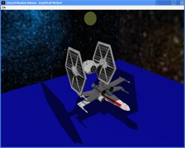 Depth-fail stencil shadow volume technique. Showcasing accurate self-shadowing and multiple occluder shadowing.
  Front faces of shadow volume drawn to give a visual appreciation of the silhouette extrusion from the point light source.
 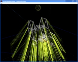 Wire frame of the occluders and the shadow volume.
 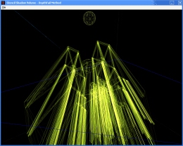 The occluder's geometries were omitted to show the front and back capping of the shadow volume. The light facing geometries forms the front cap.
 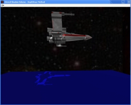 Near plane clipping of shadow volume causes errors when the camera enters the shadow volume in the depth-pass technique.
 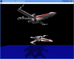 Far plane clipping of shadow volume cause errors in the depth-fail technique. Many thanks to Augustin Denis for providing the XWing and Tie fighter models. (These models are fan art)
[size="5"]Reference
[1]: Mark Kilgard, http://developer.nvi...ATT/stencil.pdf
[2]: Mark Kilgard, http://developer.nvi...ows_CEDEC_E.pdf
[3]: http://developer.nvi..._shadow_volumes
[4]: Charles Bloom, http://www.cbloom.co...adow_issues.txt
[5]: Tim Heidmann, http://developer.nvi...owsRealTime.pdf
[6]: John Carmack, http://developer.nvi...adowVolumes.txt
[7]: Bilodeau, Bill and Mike Songy. "Real Time Shadows", Creativity 1999, Creative Labs Inc. Sponsored game developer conferences, Los Angeles, California, and Surrey, England, May 1999.
[8]: Frank Crow. Shadows Algorithms for Computers Graphics. Computer Graphics, Vol. 11, No.3, Proceedings of SIGGRAPH 1977, July 1977.
[9]: Cass Everitt and Mark Kilgard, http://developer.nvi...adowVolumes.pdf
[10]: Cass Everitt and Mark Kilgard, http://developer.nvi...adowVolumes.pdf
[11]: Eric Lengyel, http://www.gamasutra.../lengyel_01.htm
[12]: Eric Lengyel, "Mathematics for 3D Game Programming & Computer Graphics", Charles River Media, 2002
[13]: Tomas Moller, Eric Haines. "Realtime Rendering", 2[sup]nd[/sup] Edition, A K Peters Ltd, 2002, ISBN: 1-56881-182-9.
[14]: Wolfgang F. Engel, Amir Geva and Andre LaMothe. "Beginning Direct3D Game Programming", Prima Publishing, 2001, ISBN: 0-7615-3191-2.
[15]: Wolfgang F. Engel. "Direct3D ShaderX Vertex and Pixel Shader Tips and Tricks", Wordware Publishing Inc, 2002.
[16]: Power Render X game engine. http://www.powerrend...m/prx/index.htm
[17]: Gamasutra website. http://www.gamasutra.com/


I can't see this article correctly