An Introduction
Of the many effects in computer graphics, the water effect is one that will definitely catch the viewer's attention. It simulates the behavior of water when it is disturbed.
This article consists of two parts. The first part describes how the behavior of water is simulated. The second part describes how you can calculate the refraction of light when it hits a transparent surface. Together they provide you with the knowledge to program an eye-catching simulation.
Part 1 - How Waves Are Simulated
This mechanism behind this effect is remarkably simple. It is so simple, that I believe that it was invented by accident while experimenting with area sampling. But before I dive into the calculations behind the wave simulation, I will tell you something about area sampling.
Area Sampling
Area sampling is a very common algorithm in computer graphics. Considering a two-dimensional map, the value at (x, y) is affected by values surrounding position (x, y), such as (x+1,y), (x-1,y), (x,y+1) and (x,y-1). Our wave simulation actually works in three dimensions, but I'll get to that later.
Area Sampling Example: A Simple Blur
Blurring a map is very simple. You'll need two maps: one containing the data you want to blur, and one for the resulting map. The algorithm (using five sample values) looks like this:
ResultMap[x, y] := ( SourceMap[x, y] +

				 	SourceMap[x+1, y] +

				 	SourceMap[x-1, y] +

				 	SourceMap[x, y+1] +

				 	SourceMap[x, y-1] ) DIV 5
In plain English: the value at (x, y) depends on the average value of surrounding values. Sure, things get a bit more complicated when you want to blur images, but you get the idea.
Creating a wave simulation is basically the same, but the value at (x, y) is calculated in a different manner. Earlier I mentioned that our wave simulation works in three dimensions. Well, our third dimension is time. In other words: while calculating our wave simulation, we have to know how the waves looked like one moment earlier. The resulting map becomes the source map for the next frame.
This is the actual wave simulation algorithm:
ResultMap[x, y] := (( CurrentSourceMap[x+1, y] +

					  CurrentSourceMap[x-1, y] +

					  CurrentSourceMap[x, y+1] +

					  CurrentSourceMap[x, y-1] ) DIV 2 ) -

					  PreviousResultMap[x, y]
You'll notice that the first four values obtained from the current source map are divided by two. This results in a value twice the average. Next, we subtract the value at our working location (x, y) from the previous result map. This produces a new value. Look at figure a and b to learn how this effects the wave.
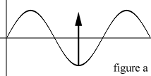
The horizontal gray line represents the average height of the waves. If the previous value at (x, y) was lower than average, then the wave will rise towards average level, as shown in figure a.
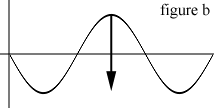
If the previous value at (x, y) was higher than average, as shown in figure b, the wave will drop towards average level.
Damping
Every time a wave moves up and down, its energy is distributed over a growing area. This means that the amplitude of the wave drops until the wave levels out. Using a damping factor simulates this. The factor, a certain amount or percentage of the amplitude, is subtracted from the current amplitude to let high amplitudes die out fast, and low amplitudes die out slow. In the example below, one sixteenth of the amplitude is subtracted each time it moves.
Wave Simulation Example
The following code fragment originally included some inline assembler, but I replaced it by native Pascal code so it can be easily ported to any language and/or platform.
.

.

const

  MAXX = 320;			 	{ Width and height of WaveMap }

  MAXY = 240;

  DAMP = 16;				  { Damping factor }


{ Define WaveMap[frame, x, y] and frame-indices }

var

  WaveMap: Array[0..1, 0..(MAXX-1), 0..(MAXY-1)] of SmallInt;

  CT, NW: SmallInt;


.

.

procedure UpdateWaveMap;

var

  x,y,n: Smallint;

begin

  { Skip the edges to allow area sampling }

  for y := 1 to MAXY-1 do begin

	for x := 1 to MAXX-1 do begin

	  n := ( WaveMap[CT,x-1,y] +

		 	WaveMap[CT,x+1,y] +

		 	WaveMap[CT,x,y-1] +

		 	WaveMap[CT,x,y+1] ) div 2 -

		 	WaveMap[NW,x,y];


	  n := n - (n div DAMP);


	  WaveMap[NW,x,y] := n;

	end;

  end;

end;

.

.
When this code is executed, you would render the result to an image buffer. How this is done is explained in part 2. Important is that you swap the source and result map for the next iteration, after rendering the image:
Temporary_Value := CT;

CT := NW;

NW := Temporary_Value;
But what do CT and NW mean? CT and NW are variables that point to different wavemaps. CT is the current wavemap, which contains the data we need to generate the new wavemap, pointed to by NW. CT and NW can hold two values, 0 and 1, and can never be the same. Because we swap the maps after each iteration, the new wavemap contains the data of the wavemap generated before the current wavemap. I realize that this might sound complicated, but it really isn't.
Getting It To Move
The procedure above simply levels out the waves. So, how can we make the whole thing move? Exactly, by lowering values in the wavemap. An undisturbed wavemap contains only zero's. To create a wave, just pick a random location and change the value like this:
WaveMap[x, y] := -100;The higher the value the bigger the waves.
Part 2 - Transparent Surface Ray-Tracing
Now we have our wavemap, we want to have some fun with it. We take a beam of light and let it pass through the surface vertically. Because water has a higher density than air, the beam refracts towards the surface normal, and we can calculate where the beam hits whatever is under there (an image, for example).
First we have to find out what the angle between the incoming light and the surface normal is (figure c).
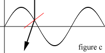
In figure c, the red line represents the surface normal. The vertical line running through the wavemap represents the incoming light, and the arrow connected to the vertical line is the refracted beam. As you can see, the angle between the refracted beam and the surface normal is smaller than the angle between the incoming beam and the surface normal.
Determining The Angle Of The Incoming Light
This is done by measuring the difference in height between (x, y) and (x-1, y), and between (x, y) and (x, y-1). This gives us a triangle with a base of 1. The angle equals arctan( height difference / 1 ), or arctan( height difference ). Look at figure d for an explanation:
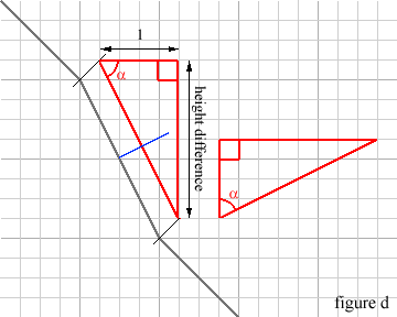
Calculating the angle between the surface normal and the incoming light is very simple in our case. If we draw an imaginary triangle as shown here in red, all we need to do is determine alpha. We get the tangent of alpha when we divide y (height difference) by x (1). In other words, the height difference is the tangent of alpha, and alpha is ArcTan( height difference ).
To convince you of the fact that this is actually the angle between the surface normal and the incoming light, I rotated the red triangle 90 degrees counter-clockwise. As you can see, the hypothenusa runs parallel to the surface normal.
Next, we calculate the refraction. If you remember your high school physics, you know that:
[bquote]refraction index = sin( angle of incoming light ) / sin( angle of refracted light )[/bquote]
so that the angle of the refracted beam can be calculated like this:
[bquote]angle of refracted light = arcsin( sin( angle of incoming light ) / refraction index )[/bquote]
where the refraction index is that of water: 2.0.
Third, we need to calculate where the refracted beam hits the image, or its relative position to the place where the incoming light beam originally entered:
[bquote]displacement = tan( angle of refracted beam ) * height difference[/bquote]
Transparent Surface Ray-Tracing Example
The following code fragment is not optimized, because you would miss out on all the important details of the calculation.
for y := 1 to MAXY-1 do begin

  for x := 1 to MAXX-1 do begin

	xDiff := Trunc(WaveMap[x+1, y] - WaveMap[x, y]);

	yDiff := Trunc(WaveMap[x, y+1] - WaveMap[x, y]);


	xAngle := arctan( xDiff );

	xRefraction := arcsin( sin( xAngle ) / rIndex );

	xDisplace := Trunc( tan( xRefraction ) * xDiff );


	yAngle := arctan( yDiff );

	yRefraction := arcsin( sin( yAngle ) / rIndex );

	yDisplace := Trunc( tan( yRefraction ) * yDiff );


	if xDiff < 0 then begin

	  { Current position is higher - Clockwise rotation }

	  if yDiff < 0 then

		newcolor := BackgroundImage[x-xDisplace, y-yDisplace]

	  else

		newcolor := BackgroundImage[x-xDisplace, y+yDisplace]

	end else begin

	  { Current position is lower - Counterclockwise rotation }

	  if yDiff < 0 then

		newcolor := BackgroundImage[x+xDisplace, y-yDisplace]

	  else

		newcolor := BackgroundImage[x+xDisplace, y+yDisplace]

	end;


	TargetImage[x, y] := newcolor;

  end;

end;
The attached files demonstrate these effects.
