One of the
most difficult programming difficulties you will face is that of representing a 3D world on that 2D screen in front of you. It requires some linear alegbra that may be difficult for some, so I will spend some bytes explaining the mathematics computations of using matricies in addition to the equations to get you going. This document is intended to be an aid to anyone programming in any language, as a result it will use mathmatic notation. If you are worthy of using these routines, you ought to be able to get them into your favorite language. All I ask is that you pay a little tribute to your programming buddies in VLA.
If you aren't a math person, skip to the end and get the final equations. Just be forewarned, implementing these equations into a coherent 3D world is hard enough when you understand the mathematics behind them...
REAL PROGRAMMERS AREN'T AFRAID OF MATH
3D Coordinates
Just so we all understand each other, 3D is defined in of course three directions, we'll call them (X,Y,Z). X will be the horizontal plane of your screen, Z will stretch vertically, and Y will extend out of and into your screen. Got it? Hope so, because it gets a bit tricky now. The next system is called Spherical Coordinates it is defined by angles and distance in ([font=Times New Roman]
q,
f,
r[/font]) These Greek letters are Theta, Phi, and Rho.
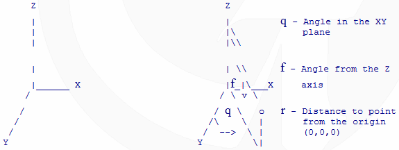
To relate the two systems you can use these equations.
If these don't seem right, do a couple of example problems for yourself, it should make since after a bit of trig.
Matrix Notation
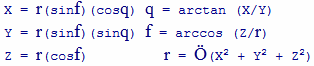
Let's say I can define Xt and Yt with the equations:

The matrix notation for this system of equations would be:
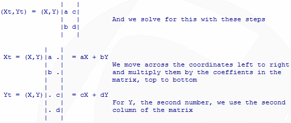
We can also multiply matrices in this fashion
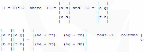
This product is dependent on position, so that means that T1*T2 *DOES NOT* equal T2*T1
In English, the process above went like this, we move left to right in the first matrix, T1, and top to bottom in the second, T2. AE + CF is our first position.
The numbers in the first row are multiplied by the numbers in the first column. 1st * 1st + 2nd * 2nd is our first value for the new matrix. Then you repeat the process for the next column of the second matrix.
After that, you move down to the next row of the first matrix, and multiply it by the 1st column of the second matrix. You then do the same for the next column of the second matrix. This process is repeated until you've done all of the rows and columns.
If this is your introduction to matrices, don't feel bad if you're a bit confused. They are a different mode of thinking about equations. The operations above give the same results as if you were to do the long hand algebra to solve them. It may seem a bit more difficult for these examples, but when you get to systems of equations with many variables, this way is MUCH faster to compute. Trust me, especially when you make your program do it.
So, now you have the basic math....
One important point for these matrices below. I will use a homogeneous coordinate system, (X/r, Y/r, Z/r, r) Now I'll use r=1, so nothing will really be different in my calculations, but you need to understand the purpose.
This form is very convenient for the translations and rotation equations we will need to do because it allows for scaling of our points with respect to a center point.
Consider a point (2,2,2) in an object centered at (1,1,1). If we were to scale the X direction by 3,(the X length to the center is 3 times what it was) the point we want would be (4,2,2). Our new X = 3*(OldX-CenterX). Without the added factor of the homogeneous system, calculations assume all objects are centered at the origin, so our point would have turned out to be (6,2,2), NOT the one we wanted. So that's why we are going to do it that way.
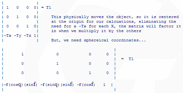
Translation
We will start with translation from the origin. Most objects are not at (0,0,0,1), so we'll call their center (Tx,Ty,Tz,1).
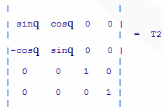
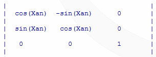
XY Clockwise Rotation
This will be our first rotation, about the Z-Axis
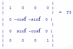
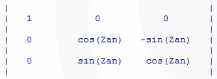
YZ Counter-Clockwise Rotation
Now we rotate about the X axis
Notice that with two rotations that we can get any position in 3D space.
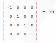
Left Hand Correction
This will flip the X coordinates. Think about when you look into the mirror, your left hand looks like your right. These rotations do the same thing, so by flipping the X, it will make your X move right when you increase it's value.
The Final Viewing Matrix
This is the net transformation matrix for our viewing perspective The math for this one is really messy, and I would need to go over even more matrix stuff to get it reduced, so I will ask you to trust my calculations
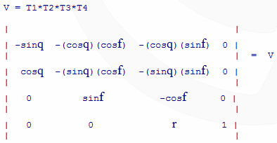
Let's say our original (X,Y,Z,1) were just that, and the point after the rotation is (Xv,Yv,Zv,1)
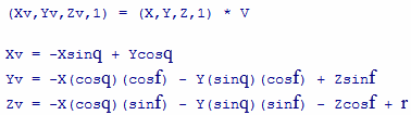
Some people have had trouble concepts of this implimentation, so I have another way of setting up the equations. This works off of the straight X,Y, and Z coordinates too, but uses another angle.
We will define the following variables
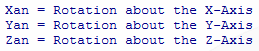
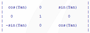
Rotation about the Y Axis
Rotation about the Z Axis
Rotation about the X Axis
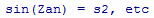
For simplification, lets call sin(Yan) = s1, cos(Xan) = c3,
Final Rotation Matrix
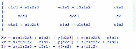
Where Xv,Yv, and Zv are the final rotated points and the little x,y,z are the original points.
Normal Vectors
So, now you have the rotation equations... But, how do we make it fast? Well, one of the best optimizations you can implement is plane elimination.
It boils down to not displaying the planes that won't be seen. With that said, here comes more math....
BE A MAN, KNOW YOUR NORMALS
A 'normal' vector is perpendicular to a plane. Imagine the face of a clock as a plane. Take your right hand and point your thumb toward yourself and the other end toward the clock. Now curl your fingers in the counter-clockwise direction. Your thumb is pointing in the direction of the normal vector. This is called 'The Right Hand Rule' and it is the basis for figuring the facing of planes.
A plane can be determined with three points, try it. That's the minimum you need, so that's what we will base our process on. Now if we have a line segment, we could move it to the origin, maintaining it's direction and length by subtracting the (X,Y,Z) of one of the points from both ends. This is our definition of a vector. A line segment, starting at the origin and extending in the direction (X,Y,Z).
Here will be our plane, built from the three points below.
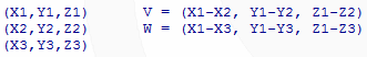
So, we have our three points that define a plane. From these points we create two vectors V and W. Now if you where to use the right hand rule with these vectors, pointing your fingers in the direction of V and curling them toward the direction of W, you would have the direction of the Normal vector. This vector is perpendicular to both vectors, and since we have defined the plane by these vectors, the normal is perpendicular to the plane as well. The process of finding the normal vector is called the 'Cross Product' and it is of this form:
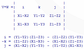
The Normal to the plane is (i,-k,j)
NOTE: V*W *DOESN'T* equal W*V, it will be pointing in the negative direction. To prove that to yourself, let's go back to how I explained it before. We pointed in the direction of V and curled our fingers toward W, the normal vector in the direction of your thumb. Try it in the direction of W, toward V. It should be in the opposite direction. Your normal, still perpendicular to both vectors, but it is negative. If you use in your program, you will have the planes appearing when they shouldn't and disappearing when they are coming into view.
So, now that we have a way to determine the direction of the plane, how do we hide the plane? If the angle between the view point and the normal is greater than 90 degrees, don't show it. One quick way that I always use is to place the view point on an axis. I typically set the Z axis to come out of the screen, Y up and X across. Set the view point to be at a positive point on the Z and then, if that normal vector has Z greater than zero, I display it, otherwise I skip to the next one.
Is also has an application in shading. If you define a light source, just like the view point, you find the angle the normal and the light form. Since you don't usually just want two colors, our 90 degree trick won't work for you, but by finding this angle, and dividing all of the possible angles by the number of colors you will allow in the shading, that color can be assigned to the plane and, presto-chango, it looks like you know what your doing...
As you do your rotations, just rotate the coordinates of the normal and that will keep everything updated.
Tips To Speed-Up Your Routines
Pre-Calculate as many values as possible
The main limitation you will have is the speed of your math, using precalculated values like Normals, Sin/Cos charts, and distance from the origin are all good candidates.
If you can get away with using a math-coprocessor, well...
This will greatly increase the speed of your routine. Unfortunately, not everyone has one.
Only figure values once
If you multiply (Sinq)(Cosq) and will use that same value later, by all means, keep it and use it then instead of doing the multiplication again.
Another thing to keep in mind
The order of rotations *DOES* make a difference. Try it out and you'll understand. Also, when you start to use these routines, you'll find yourself making arrays of points and plane structures.
Counterockwise points
Be sure to list your points for the planes in counter-clockwise order. If you don't, not all of your planes will display correctly when you start hiding planes.
And as always, be clever
Just watch out, because when you have clever ideas you can lose a foot. My brother once had a clever idea to cut his toe nails with an axe and he lost his foot.