The Data
From a visual standpoint, the Kinect provides three different types of data directly:
- Color Images
- Depth Images
- Joint Frames
The first two items are quite commonly referred to when people discuss the Kinect. It has a standard RGB camera, along with a lower resolution depth camera (it is actually just an infrared camera, which is used to produce depth values... but I normally refer to it as a depth camera). In my tests, I use the 640x480 color image with the 320x240 depth image configuration. These images are essentially received from the Kinect SDK by means of events. When a new image is ready for pickup by the application, the event is signaled and the data can be retrieved. So far so good.
The third data type is not as commonly discussed, although it may well be the most important aspect of the Microsoft version of the Kinect SDK. Microsoft provides a specialized method for processing the depth data to determine the location of the various joints of the people that are within view. The SDK will do this skeletal tracking for two people simultaneously, with simpler processing done for other people in the background. But this is really the best part about using this SDK - you get very good skeletal tracking more or less for free (free in the sense that you don't have to write the code to do it!).
The data for a set of joints is provided in the same event signaling mechanism as the depth data. Here is the structure that provides the joint data:
typedef struct _NUI_SKELETON_FRAME {
	LARGE_INTEGER liTimeStamp;
	DWORD dwFrameNumber;
	DWORD dwFlags;
	Vector4 vFloorClipPlane;
	Vector4 vNormalToGravity;
	NUI_SKELETON_DATA SkeletonData [NUI_SKELETON_COUNT];
} NUI_SKELETON_FRAME;

typedef struct _NUI_SKELETON_DATA {
	NUI_SKELETON_TRACKING_STATE eTrackingState;
	DWORD dwTrackingID;
	DWORD dwEnrollmentIndex_NotUsed;
	DWORD dwUserIndex;
	Vector4 Position;
	Vector4 SkeletonPositions[NUI_SKELETON_POSITION_COUNT];
	NUI_SKELETON_POSITION_TRACKING_STATE eSkeletonPositionTrackingState[NUI_SKELETON_POSITION_COUNT];
	DWORD dwQualityFlags;
} NUI_SKELETON_DATA;
When a depth image frame has been processed, we receive a NUI_SKELETON_FRAME, which will contain a number of NUI_SKELETON_DATA structures. The joint information can be attained in the NUI_SKELETON_DATA.SkeletonPositions[n] member, and these are only the positions of the joints. Most graphics programmers would be familiar with vertex skinning, in which you utilize the position and orientation at each joint - but the Kinect is different. It provides the basic information needed to identify gestures (the positions), and nothing more. If you want to find the orientations, you need to do it yourself... In any case, the positions are enough to know what the person is doing, so we will work with it

So Where Exactly Is That Data???
So we now have three separate pieces of data that all describe the same thing: the scene visible to Kinect. The trouble is, none of these three are in the same frame of reference. Those two images (color and depth) seem to be quite well lined up - but they aren't really. The two cameras themselves that take the images are offset from one another, which means the things in their viewing plane have different frames of reference. In terms of graphics programming, the contents of their images are projected versions of the scene in view space, where the view space origins are at the center of each camera.
That means that you can't look at the depth image pixel (10,20) and look at the color image pixel (20,40) and be looking at the same point in the scene. There is actually also a delta rotation between the two cameras too (since they aren't perfectly aligned to one another) not to mention the fact that there are separate lens and sensor orientation differences between them too - at one point it seemed quite hopeless to find a useful solution to match the elements of these two images together... Sure there are lots of ways to perform stereo calibration and rectification of two cameras, but who wants to do all that for every Kinect that gets used? Not me...
Fortunately, there is a method available in the SDK to map from depth image coordinates to color coordinates using the factory calibration information (which is apparently available within each Kinect to the SDK). The NuiImageGetColorPixelCoordinatesFromDepthPixel method provides a one-way mapping of depth to color, but no possibility of color to depth. Why not, you may ask? Because when you only have a color image, you only have its (x,y) position. Since we don't have the depth value at that pixel, the best we can do is determine a line in the depth image that is possible to correspond to the color image. When we map from depth to color, naturally we have the (x,y,z) coordinates, which can be mapped to a single point in the color image.
That is a good first step - mapping from depth image coordinates to color image coordinates lets us look up the color of a point in the depth image. The next logical step to take is to map the depth pixels to a metric world space. (Here we are referring to the depth camera's view space as the world space simply for the sake of simplicity. The depth data is formulated in this space, so it makes sense to choose the depth camera as the world space origin...) This ability would allow for a 3D surface reconstruction of the depth image, which is one of the views that are commonly shown in Kinect demos. This is also accomplished through another SDK method, this time taken from the MSR_NuiSkeleton.h header file:
// Assuming a pixel resolution of 320x240
// x_meters = (x_pixelcoord - 160) * NUI_CAMERA_DEPTH_IMAGE_TO_SKELETON_MULTIPLIER_320x240 * z_meters;
// y_meters = (y_pixelcoord - 120) * NUI_CAMERA_DEPTH_IMAGE_TO_SKELETON_MULTIPLIER_320x240 * z_meters;
#define NUI_CAMERA_DEPTH_IMAGE_TO_SKELETON_MULTIPLIER_320x240 (NUI_CAMERA_DEPTH_NOMINAL_INVERSE_FOCAL_LENGTH_IN_PIXELS)

// Assuming a pixel resolution of 320x240
// x_pixelcoord = (x_meters) * NUI_CAMERA_SKELETON_TO_DEPTH_IMAGE_MULTIPLIER_320x240 / z_meters + 160;
// y_pixelcoord = (y_meters) * NUI_CAMERA_SKELETON_TO_DEPTH_IMAGE_MULTIPLIER_320x240 / z_meters + 120;
#define NUI_CAMERA_SKELETON_TO_DEPTH_IMAGE_MULTIPLIER_320x240 (NUI_CAMERA_DEPTH_NOMINAL_FOCAL_LENGTH_IN_PIXELS)
These two functions provide simple methods for implementing a pinhole camera model projection and unprojection. I am using these equations in a shader program instead of directly using them, but the comments on the comments here provide a simple description of what is being done to transform back and forth from depth image coordinates to world space coordinates. With these in hand, we can produce a 3D reconstruction of the scene that the Kinect can see, and then rotate around it or whatever we want to do - in fact, this 3D scene can be directly used in a game or other application if you so desire. Since we have a mapping to the color image, we can even produce a colored surface reconstruction. That's pretty nifty for just a little bit of math...
But wait - what about the joint information? How do we map the positions that we get from the SDK into our world space? It turns out that the data is provided in the same coordinate space as our reconstructed surface - it is a metric space with the depth camera at its origin. So the joint data is directly compatible with our 3D surface reconstruction! In the end, this makes sense due to the fact that the joint data is generated solely from the depth data - it shouldn't be in any other coordinate space than that of the depth camera.
What Can I Do With That Data???
That was a long way to describe how to convert and relate the various data pieces together. So what can we do with them now that we have them? We can build an interesting demo program
here is the result of all this writing: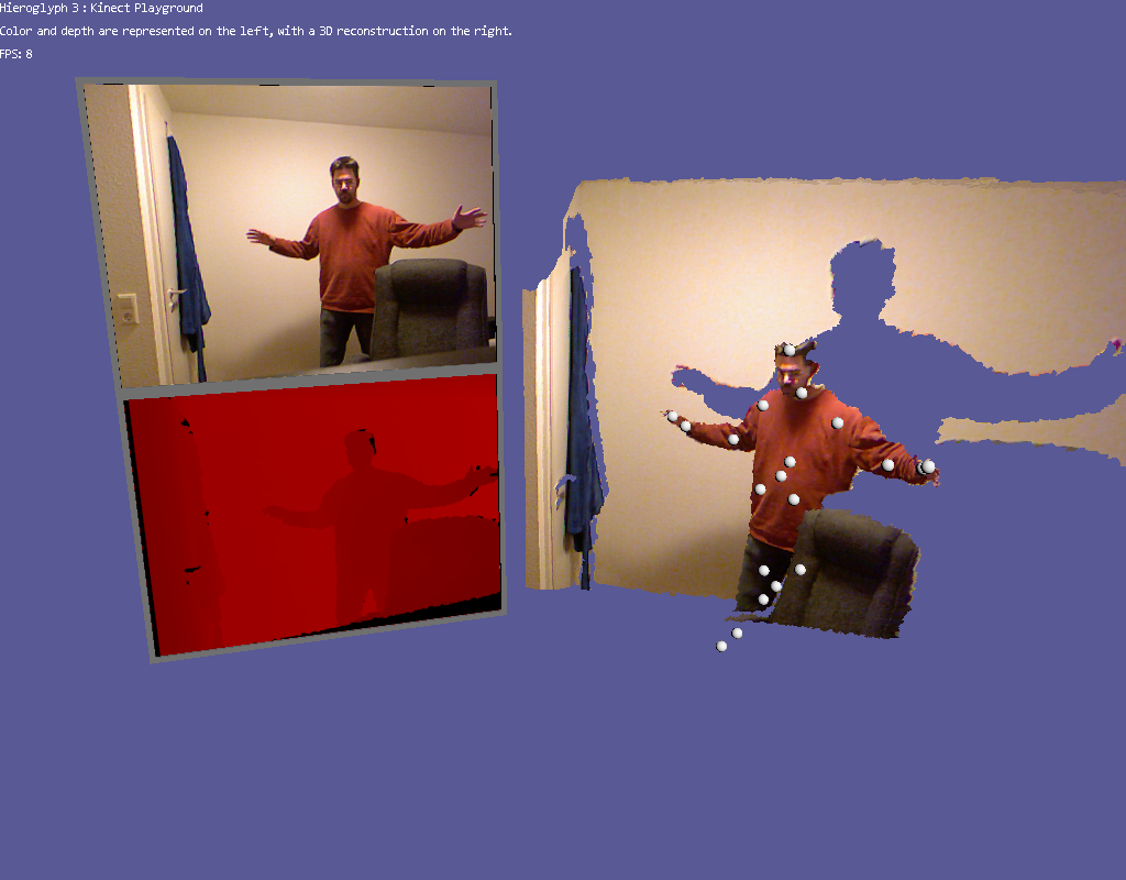
On the left are the color and depth buffers (scaled to be the same physical size despite their resolution differences). On the right is the reconstructed scene, with the color value sampled and applied to the surface. Finally, each of the joints that are available are rendered (without depth test enabled so you can see them - otherwise they would be behind the reconstructed surface!) as individual spheres. Now, with all of this stuff spelled out, what do we do with the data other than display it?
That will be a topic for another entry
In the mean time, if you have a Kinect then head over to the Hieroglyph 3 codeplex page and try it out!