 LCD Timing
Last time I discussed the hardware I mentioned I had LCD timing issues. I have finally resolved them, but this has been the most time consuming part of the project so far.
The first thing to sort out was the LCD's E pin. Once you have set up the LCD's input pins to a state where they're ready to read or write data, you need to drive this pin high. I had had some success by holding it high permanently and relying on the Z80 to set all the other to the right state at roughly the same moment, but this was inaccurate and resulted in occasional display glitching.
Consulting the datasheet, it appears that once the input pins are ready E needs to be held low for at least 450nS and then needs to be driven high for at least 450nS. Hmm. During an I/O request (and once the Z80 has prepared the address and data bus) there's a delay of 1 clock cycle, then /IORQ is held low for about 2.5 CPU cycles. That is the window of opportunity. I have connected a binary counter to the Z80's clock signal and take the least significant bit of the output - every clock cycle this output toggles between a low and a low, effectively halving the CPU clock rate. I then connect the counter's reset pin (which overrides the clock input and forces it to output zero) to /IORQ. The result is that when the Z80 is not accessing hardware the counter is held in its reset state, and E is held low. When the Z80 holds /IORQ low, the counter starts up and outputs a zero for one CPU cycle, outputs a one for the next CPU cycle, then outputs a zero for the next half clock cycle at which point /IORQ goes high again and it is back to zero anyway. This is exactly what's needed!
This also allows us to calculate the maximum CPU clock rate. If we are generous and allow E to be low for 500nS then high for 500nS, that gives us a CPU clock rate of 1/500nS=2MHz.
Anyhow, that's one problem resolved, but there was still one nasty bug. When reading from the LCD it would occasionally end up writing to the area that was being read or, in worse cases, the Z80 would "crash". The LCD has a R/#W pin that is held high when reading and held low when writing. I had connected it directly to the Z80's /WR pin, which is high normally and low when writing. The problem here is "normally" as the LCD was expecting to be read even when the Z80 wasn't requesting a /RD. When being read, the LCD expects to put something onto the data bus, and it appeared that it kept thinking that it needed to put something on the bus when it wasn't needed. This caused fighting with the other chips that were trying to put their own values on the data bus, hence the crashes as the Z80 received invalid data.
The answer was very easy; simply connect the Z80's /RD pin to the LCD's R/#W pin via a NOT gate. In the default state the pin is held low (LCD expects a write and leaves the data bus alone), and only goes high during a /RD. The LCD interface is now very robust.
CPU Clock
Above I mention the calculation for the maximum clock rate. Rather than use the 555 for timing, I switched to using a 10MHz crystal resonator oscillator. I'm using the serial resonant circuit from z80.info with a 74F04 hex inverter (second circuit down). Fortunately the counter chips I have are decade counters (ie, designed to count from 0 to 9) made up of a /2 and a /5 section. I can connect a 10MHz oscillator to the /5 section and use the output of that to drive the CPU. In the final design I'd like to add a "hardware control port" with a bit that would let the programmer choose 2MHz or 10MHz mode by setting or resetting a particular output bit (other control bits would include switching the LCD backlight on or off and a buzzer for beeping sound output).
PS/2 Ports
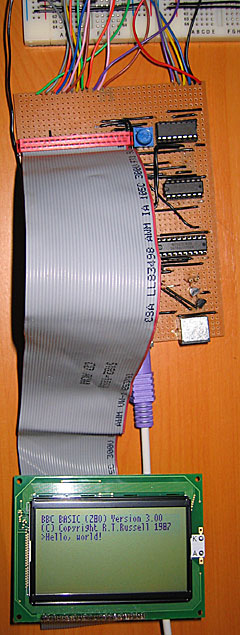
As a friend pointed out, the 8-bit open-collector I/O port (which will drive two PS/2 ports, the I2C bus and TI calculator link port) had a flaw - there was no resistor on the base of the output transistors. The result is that if the output latch tries to drive the transistor base high, the transistor switches on and shorts the output of the latch to ground. This was clearly a problem in the design as the LCD backlight dimmed when trying to output to these ports as they drew a excessive amount of current when effectively short-circuited. A 22K resistor between the output latch and base of the transistor fixed the problem.
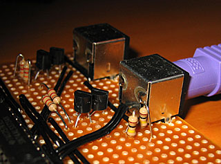
In the above photo, I've also added two 100K resistors to hold the output high when floating, but only to the foreground PS/2 port for the time being. I don't think I'll be controlling a mouse yet!
Revised OS
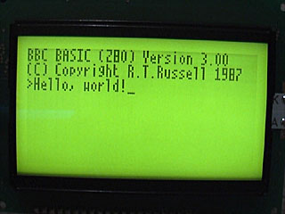
With a little modification of the Emerson PS/2 library I've got a basic keyboard driver up and running on the hardware. All the OS does for the moment is check for keys and display them on the screen. It's currently hard-coded to the UK layout, as I haven't yet decided how I'm going to handle storage and by keeping the layout in ROM it at least frees up a few hundred bytes of RAM that would otherwise need to be there for the scancode translation tables.
Click for video (1.76MB WMV)


Unfortunately, I have no clue what I'm doing when it comes to hardware land.
So where did you learn all this junk from? Any good references?