dsPIC33 VDC with GLCD or PAL TV output

Published July 04, 2010
Advertisement
I have currently been using some terminal emulation software on my PC to see the output of the Z80 computer. It seems a little silly to rely on a large multi-gigahertz, multi-megabyte machine just to display the output from a machine at the megahertz and kilobyte end of the scale. I had previously done some work with a dsPIC33 to drive a 320?240 pixel graphical LCD so dug out its breadboard and dusted off the code to try to make something of it.

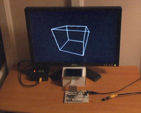
Inspired by John Burton's recent experiments with PAL TV output I decided that the first thing I should do is add support for TV output. The graphical LCD is nice but a little small and responds to pixel changes rather slowly, making animation very blurry.

dsPIC33 VDC demo
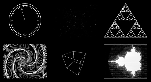
I think the results are reasonably good. A lot of the code is shared with the old LCD driving code, which means that the LCD demos work fine with the TV too. Fortunately, retracing the TV is a much less CPU-intensive job than retracing the LCD. The PIC has an SPI peripheral that allows you to clock out eight or sixteen bits a bit at a time at a selected speed by writing to a single register, which is great for clocking out the pixel data on each scanline. Even better are the PIC's DMA channels, which allow you to output a selected number of bytes or words to a selected peripheral from a specified location in RAM with no CPU involvement; all I need to do on each line is to copy a complete scanline to the DMA memory, initiate a transfer from this memory to the SPI peripheral and the job is as good as done. Using the DMA hardware as opposed to writing to the SPI registers directly reduced the rendering time of the Mandelbrot fractal part of the demo from 33 seconds to 18 seconds.

One problem I haven't been able to resolve is that the PIC inserts a small delay between every DMA/SPI transfer, which results in every sixteenth pixel being a bit wider than the fifteen before it. This is especially noticed on dithered regions. If I write to the SPI registers directly this delay vanishes. I'm not sure if the picture quality increase is worth the loss of performance, so I'd rather find a proper fix for this! For the time being, here's a video of the demo as it currently runs:

">
Click here to view the video on YouTube
The TV contains a 75? resistor to ground on its composite video input. Two resistors are used on two PIC pins to form a voltage divider to produce the required output voltages (0V for sync, 0.3V for black and 1V for white). When the TV is disconnected the output of the circuit is 3.3V (the supply voltage, equivalent to a logic "high") as there's no load resistance to pull it to the correct 0.3V (a logic "low"). This can be used to periodically check whether a TV is connected and to switch between the LCD and TV output modes.

The above is rather vague, and I would recommend Rickard Gun?e's article entitled How to generate video signals in software using PIC for more detailed information! The code for the demo can be downloaded from my website for those who are interested.

Update: I've updated my code to use the SPI peripheral in slave mode and use a timer and output compare unit to generate the clock signal. This regular clock signal produces pixels of identical sizes ? the new code can be downloaded here.
0 likes 4 comments

Comments

jbb
That's really good work :)

I looked at using the SPI hardware on mine but for some reason thought that SPI used start and stop bits which wouldn't work at all for this and I don't think my PIC has DMA unless I somehow missed it. So I ended up writing the whole line out pixel by pixel in assembly code. I shall read the SPI datasheet again.

I like that you've not only got the TV out to work but displayed something interesting too. That's usually the point where I stop.

When you don't use DMA are you using interrupts to refill the SPI buffer when it empties? I suspect the isn't fast enough to keep up with that at the speed needed for TV output?

July 05, 2010 02:08 AM
benryves
Quote:Original post by jbb
I looked at using the SPI hardware on mine but for some reason thought that SPI used start and stop bits which wouldn't work at all for this and I don't think my PIC has DMA unless I somehow missed it. So I ended up writing the whole line out pixel by pixel in assembly code.
The advantage of this is that when you have timing problems it's down to your code so is fixable. I haven't found a way to fix the stretched sixteenth pixel yet. One problem I did run into with the DMA method is that you can't get away with only writing to the SPI peripheral; SPI is by its very nature bidirectional and the DMA transfer stops if the receive buffer overflows (when writing to the SPI buffer directly you can ignore the overflow). I found the easiest way was to set up two DMA channels, one to write to SPI and the other to read. Using an interrupt to perform dummy reads of the SPI buffer to clear the overflow flag was too slow.

Speaking of timing problems, I found it interesting that you managed to get away with the internal oscillator. My initial tests (a solid white column in the middle of the screen) had very wobbly edges when using the internal 7.3MHz FRC oscillator, and an external 8MHz ceramic resonator was not much better. I ended up using a 10MHz crystal instead.

Quote:I like that you've not only got the TV out to work but displayed something interesting too. That's usually the point where I stop.
I wouldn't say that, your clock seemed a good demonstration of your code! The starfield is the only addition to this from the old LCD code demos.

Quote:When you don't use DMA are you using interrupts to refill the SPI buffer when it empties? I suspect the isn't fast enough to keep up with that at the speed needed for TV output?
Indeed it isn't. The SPITBF flag is cleared when the dsPIC has read the value from the SPIxBUF (which it does immediately before outputting the value) so you have plenty of time to top it up with the next sixteen bits. The particular dsPIC I'm using has a bug, however; the SPITBF flag is not set immediately after writing to SPIxBUF, so you need to write to the buffer, wait for the flag to be set, wait for the flag to be cleared, then write the next word to the buffer.
July 05, 2010 05:10 AM
jbb
The PIC24FJ64GB002 appears to have a higher precision internal oscillator than some of the other variations, I believe this is to make it possible to use the USB peripheral with the internal oscillator as USB requires fairly accurate timing. Although the datasheet does appear to contradict itself a little on whether this is officially supported - it does seem to work though.

I did obtain a crystal to use for this, but when i got the PIC I built the usual "flash an LED" circuit first and used the internal oscillator just to minimize the number of things that could fail the first time I used the chip. I always meant to add the crystal at some point but as I never had a problem with it I never thought to :)
July 05, 2010 06:59 AM
benryves
That may explain it, yes. [smile]

I've updated my code to use the SPI peripheral in slave mode and use a timer and output compare unit to generate the clock signal. This regular clock signal produces pixels of identical sizes — the new code can be downloaded here.
July 05, 2010 07:22 PM
You must log in to join the conversation.
Don't have a GameDev.net account? Sign up!
Advertisement