VGA output for the dsPIC33 VDC

Published July 25, 2010
Advertisement
I have spent quite a while working on different projects that generate PAL video signals in software. This may seem a bit odd if you consider the fact that I don't own a TV, so tend to rely on a video capture card or VGA box to see the output of these projects on a computer monitor -- something I do have a fair number of.

This reliance on another piece of technology between my project and the display device is not something I'm too keen on, so have spent some time adding native 640x480 60Hz VGA output to my dsPIC33 video display controller.

VGA monitor showing the output of the dsPIC33 VDC
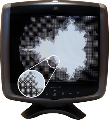
Another advantage of using a VGA monitor directly is that individual pixels are shown very crisply, unlike my video capture card or VGA box which tend to blur the image horizontally. This is shown in the zoomed in part of the above photo.

Generating a video signal for a VGA monitor is easier than generating a composite video signal for a PAL TV, as there are distinct pins for the image data, horizontal sync and vertical sync. One problem I did have, however, is with the length of the vertical sync pulse. I started with a very brief pulse (the same duration as the horizontal sync pulse) which worked fine with my old analogue CRT monitors but didn't work at all with my modern LCD monitor. The documentation I was using for timing information indicated that there were "two scanlines" for vertical sync so I extended the pulse to last for those two frames, which worked on the LCD but didn't on the CRTs. My final compromise has been to assert the vertical sync pin for the duration of a single scanline, which seems to work on all of my monitors.

dsPIC33 VDC on a breadboard
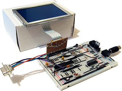
When connected to a TV two microcontroller pins are used to drive a single load (composite input). When connected to a VGA monitor, however, a single microcontroller pin is used to drive three loads (red, green and blue inputs). I thought it prudent to check the datasheet for the dsPIC before connecting this increased load to the output pin where I was surprised to discover that the maximum source or sink current for each output pin is a measly 4mA -- not even enough to drive an LED! I have added a buffer to each video output pin to protect the dsPIC -- any buffer capable of sourcing up to 30mA or so should be sufficient (I'm using a 74F125, which can be seen in the bottom right of the above photo). I had previously been occasionally using the video output pins as inputs to check if there is a load on the output or not (such a load would indicate whether a TV or VGA monitor is plugged in or not) but I can no longer do this with the external buffer IC so have had to revise the circuit somewhat. Updated source code featuring the new VGA output code and an accompanying schematic are available for those who are interested!
0 likes 14 comments

Comments

jbb
Nice work.
If you are generating VGA signals then you should be able to generate RGB colour too? I expect the memory and speed requirements are a bit too high for that though?

It this going to be the output device for your z80 project at some point?

Interesting though, the PIC24 I used seems to have considerably higher rating on the I/O pins. It doesn't have the DMA ability that you were using and presumably still are?
July 26, 2010 01:42 AM
jbb
Nice work.
If you are generating VGA signals then you should be able to generate RGB colour too? I expect the memory and speed requirements are a bit too high for that though?

It this going to be the output device for your z80 project at some point?
July 26, 2010 01:43 AM
DWN
Very cool!
My query's along the same lines as jbb: on a scale of 0x0 to 0xf, what's the likelihood you'll want to go 16b vga sometime in the near future?
July 26, 2010 05:17 AM
benryves
July 26, 2010 06:26 AM
benryves
Thanks for the kind comments! [smile]
Quote:Original post by jbb
If you are generating VGA signals then you should be able to generate RGB colour too? I expect the memory and speed requirements are a bit too high for that though?

It this going to be the output device for your z80 project at some point?
Yes, RGB colour would indeed be possible but I would have to drop the resolution (or switch to a tilemap-based system) to accommodate it. As this is intended to be the output device for the Z80 computer project I'd like the horizontal resolution to be at least 320 pixels, as CP/M assumes an 80 column display and four pixels is about as narrow as I can make characters and still have legible text.

One way to easily, though expensively, add colour output would be to use three dsPICs; one containing the red channel buffer, one the green channel buffer, and another the blue channel buffer. I reckon that changing the design to one that uses external RAM would seem to be a more sensible way to do it (or finding a microcontroller that has a lot of on-board RAM).
Quote:Interesting though, the PIC24 I used seems to have considerably higher rating on the I/O pins. It doesn't have the DMA ability that you were using and presumably still are?
It did strike me as a bit odd, as I've never used a microcontroller that couldn't drive an LED directly from an I/O pin before. Yes, I'm still using the DMA feature to stream pixels out of the SPI peripheral as his reduces CPU overhead significantly. Unfortunately I can only do this in TV or VGA output modes as the LCD requires four pixels to be clocked out at a time, not one.
Quote:Original post by DWN
My query's along the same lines as jbb: on a scale of 0x0 to 0xf, what's the likelihood you'll want to go 16b vga sometime in the near future?
For this particular project, I'd go for 0, unfortunately, due to the reasons above. It's something I may well pursue in the more distant future, however!
July 26, 2010 06:27 AM
benryves
Thanks for the kind comments! [smile]
Quote:Original post by jbb
If you are generating VGA signals then you should be able to generate RGB colour too? I expect the memory and speed requirements are a bit too high for that though?

It this going to be the output device for your z80 project at some point?
Yes, RGB colour would indeed be possible but I would have to drop the resolution (or switch to a tilemap-based system) to accommodate it. As this is intended to be the output device for the Z80 computer project I'd like the horizontal resolution to be at least 320 pixels, as CP/M assumes an 80 column display and four pixels is about as narrow as I can make characters and still have legible text.

One way to easily, though expensively, add colour output would be to use three dsPICs; one containing the red channel buffer, one the green channel buffer, and another the blue channel buffer. I reckon that changing the design to one that uses external RAM would seem to be a more sensible way to do it (or finding a microcontroller that has a lot of on-board RAM).
Quote:Interesting though, the PIC24 I used seems to have considerably higher rating on the I/O pins. It doesn't have the DMA ability that you were using and presumably still are?
It did strike me as a bit odd, as I've never used a microcontroller that couldn't drive an LED directly from an I/O pin before. Yes, I'm still using the DMA feature to stream pixels out of the SPI peripheral as his reduces CPU overhead significantly. Unfortunately I can only do this in TV or VGA output modes as the LCD requires four pixels to be clocked out at a time, not one.
Quote:Original post by DWN
My query's along the same lines as jbb: on a scale of 0x0 to 0xf, what's the likelihood you'll want to go 16b vga sometime in the near future?
For this particular project, I'd go for 0x0, unfortunately, due to the reasons above. It's something I may well pursue in the more distant future, however!
July 26, 2010 06:28 AM
jbb
3mA seems to be sufficient to light a standard LED. It's clearly not going to be nearly as bright as 20mA but it's sufficient for many things.

Is VGA the same voltage levels as scart? In which case a quick calculation seems to indicate that you need about 10mA... Hmm, my arm chip might have trouble with that.

I'm looking at using my LPC1343 for video. It has serial hardware like the pic24 and at 75mhz it might be fast enough to refill the buffers on an interrupt meaning that that I can get a reasonable resolution and still get some work done during each line.

I need to obtain and build some proper connectors though. Bodging it together by pushing wires into holes in scart connectors and so on really isn't sufficient for anything other than basic testing. I don't really have the time at the moment with trying to fit it around job interviews and research but trying to fit it in because it's fun :)
July 26, 2010 08:02 AM
benryves
Quote:Original post by jbb
3mA seems to be sufficient to light a standard LED. It's clearly not going to be nearly as bright as 20mA but it's sufficient for many things.
I usually go for at least 10mA, but your point is taken.
Quote:Is VGA the same voltage levels as scart? In which case a quick calculation seems to indicate that you need about 10mA... Hmm, my arm chip might have trouble with that.
VGA is the same voltage level as SCART RGB (0.7V) which is a little lower than composite video (1V, SCART or otherwise). The impedance is the usual 75Ω.
Quote:I'm looking at using my LPC1343 for video. It has serial hardware like the pic24 and at 75mhz it might be fast enough to refill the buffers on an interrupt meaning that that I can get a reasonable resolution and still get some work done during each line.
Sounds good, I look forwards to seeing where you take it. [smile] I'm a little surprised at the amount of RAM offered, though; even the dsPIC33 I'm using has 16KB. I'm still pondering the Propeller as another option.
Quote:I need to obtain and build some proper connectors though. Bodging it together by pushing wires into holes in scart connectors and so on really isn't sufficient for anything other than basic testing. I don't really have the time at the moment with trying to fit it around job interviews and research but trying to fit it in because it's fun :)
I'd go mad (well, more mad) if I didn't have my hobbies to balance out my work; best of luck with the interviews!

My local Poundland sells SCART leads (with every pin connected) and SCART splitters; these may provide a cheap supply of SCART plugs and sockets.
July 26, 2010 08:19 AM
Extrarius
You might find it 'better' to do DMA to the PMP or to PORTB because that gives you 8 or 16 pins toggling at once. You'll need a bit of memory to store an expanded scanline (from whatever bpp you want) and a few cycles to expand each line before displaying it, but it also gives you the option of a palette for VGA (expand, say, 2 or 4 bits to 5:5:5).
Really, though, using an FPGA as a video card for the uC probably makes the most sense. Using even a low-pin inexpensive chip would allow you much more complex logic interfacing with reasonable ram buffers, etc.
July 31, 2010 01:29 AM
benryves
Part of my reason to sticking to monochrome 320?240 is that the graphical LCD that I intend to use as the primary display device is a 320?240 monochrome one. That and memory becomes a bit of a problem for higher resolutions or coloured displays. Some microcontrollers can be connected to external RAM but these tend to be fiddly SMD parts that I don't really have the equipment to work with.

That said, I would be quite interested in getting into programmable logic anyway; I can imagine how I could build a better VDC out of discrete logic and RAM chips but it would end up being physically very large and a pain to solder together. Do you have any recommendations for inexpensive FPGA equipment (if such a thing exists?) Even then I'm not sure it would be available in DIP. [sad]
July 31, 2010 10:52 AM
jbb
sparkfun.com sell some kind of FPGA on a breakout board but it's not particularly cheap at about $80 but you can get a lot of their stuff in the UK from various suppliers so maybe you can get it here. I have no knowledge about the chip on the board though, or what it's good for. Or what else you need to use one. Or about programming them :P
July 31, 2010 11:15 AM
jbb
On your last photograph you have what appears to be a socket for a composite video connector plugged directly into your breadboard. All the ones I've seen seem to be solder connections. But it's a bit small to see exactly. I had a look for such a connector a while ago and couldn't see anything suitable.

So is it what it looks like to me? And if so do you know where you got it?
August 01, 2010 12:28 PM
Extrarius
Quote:Original post by benryves
Part of my reason to sticking to monochrome 320?240 is that the graphical LCD that I intend to use as the primary display device is a 320?240 monochrome one. That and memory becomes a bit of a problem for higher resolutions or coloured displays. Some microcontrollers can be connected to external RAM but these tend to be fiddly SMD parts that I don't really have the equipment to work with.

That said, I would be quite interested in getting into programmable logic anyway; I can imagine how I could build a better VDC out of discrete logic and RAM chips but it would end up being physically very large and a pain to solder together. Do you have any recommendations for inexpensive FPGA equipment (if such a thing exists?) Even then I'm not sure it would be available in DIP. [sad]
You are correct in stating that FPGAs are rarely available in DIP packages, so you might want to avoid them if you plan on making your project into a soldered circuit board. However, there are many kits designed around FPGAs that you could use if you're fine sticking to solderless prototyping. For example, on the inexpensive end (for FPGA kits) at $200 there is Cyclone III FPGA Starter Kit which has everything you'll probably ever need out of an FPGA (including plenty of i/o pins exposed). There are several similar options available at Terasic spanning to much higher costs if you want fancier outputs and onboard peripherals, etc.
Another approach you could take (especially if you'd rather work with components) is to use adapter sockets like those a futurlec.
August 02, 2010 04:39 PM
benryves
Quote:Original post by jbb
On your last photograph you have what appears to be a socket for a composite video connector plugged directly into your breadboard.
It's a 3.5mm stereo jack socket with a 3.5mm mono jack to RCA adaptor plugged into it. I've only ever seen them available as panel mounted or line connectors, not PCB mounted, I'm afraid.
Quote:Original post by Extrarius
However, there are many kits designed around FPGAs that you could use if you're fine sticking to solderless prototyping. [...]
Thank you very much for your suggestions! I've bookmarked your reply for future reference. $199 doesn't seem bad for such a nice development kit. [smile] Ultimately I do prefer to end up with a finished project rather than a pile of breadboards so those Futurlec parts look useful for the more fiddly IC packages. Cheers!
August 03, 2010 05:17 AM
You must log in to join the conversation.
Don't have a GameDev.net account? Sign up!
Advertisement