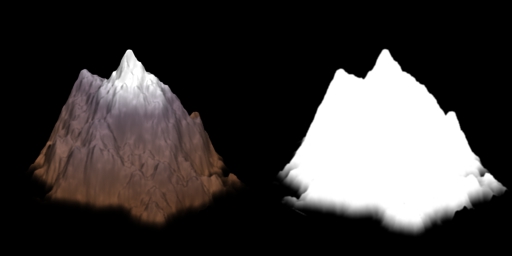
See those pixels? The ones where the alpha value is a gray value between 0 and 1? The official 3D graphics-programming term for pixels like those is "assholes." Those pixels are assholes. You see, that sprite was rendered from Blender with anti-aliasing enabled. This means that the exported alpha channel is blended at the edges. This is cool for an isometric game, because it allows "free" anti-aliasing of rendered objects, as well as smooth blending of objects that are supposed to "fade" into the background. (Refer to the bottom of that mountain, where the blend helps it to superimpose upon the ground without a harsh line edge.) When the sprites are layered together and drawn, the alpha-blending of the sprites will cause them to be smoothly composited together without harsh edges or "jaggies" caused by aliasing.
A "traditional" 2D isometric is constrained to draw back-to-front anyway, due to the layering requirements, so this anti-aliasing incurs no additional cost. The rendering algorithm of an isometric is designed for a single special case. However, this is not the case with a generalized 3D engine. When 3D objects are drawn as solids (ie, no alpha blending) it is not necessary to sort them based on depth. They can be drawn in batches, willy-nilly, and the Z-buffer will cull obstructed fragments. However, in order to implement partially transparent objects (ie, anti-aliased rendered sprites) the transparent geometry needs to be sorted back-to-front relative to the view. With a 2D isometric engine, this sorting is performed as a consequence of the rendering algorithm which iterates the scene back to front. In a general 3D engine, though, it is necessary to apply an actual sort algorithm to visible objects, and this extra step of sorting means an additional performance hit when rendering. It also means that optimization using batches of primitives becomes a little more hairy, since batches can be spatially interleaved with one another. (Imagine vegetation batches, where each batch represents one type of vegetation. The various types are all mixed up, making back-to-front sorting of the batches impossible. So the only type of alpha blending that is practical for this type of batched entity is a 1 or 0 alpha "cutout" that does not actually blend any pixels. Blending based on alpha with partial transparency will result in occasional "halos" around entities that just looks bad.)
That is why those pixels are assholes. They make the end product look good, but in so doing they force a full-scene sort that, in the case where there are lots and lots of objects on screen, may impose a rather stiff performance penalty upon rendering with a general 3D engine. This, for me, is one of the strongest arguments in favor of rolling your own, rather than using a general scene manager. Isometric cameras are extremely predictable (ie, no perspective and no arbitrary rotation means that you can always calculate the exact visible area and use a known method for iterating it back-to-front). If you can roll your own scene manager to permit the specific type of drawing required by the isometric camera, you can save yourself a great deal of processing time.
However, this particular article isn't about that. I haven't delved into Horde3D deeply enough to unravel the rendering system yet, so I couldn't say at this moment what would be required of me to roll my own scene manager using Horde3D as a basis. Instead, I want to see exactly how well the general scene manager will perform in this case.
Now, there are several ways you can do environment graphics for an isometric game that uses a 3D engine underlayer. You can use the same pre-rendered sprites that you would use in a 2D game (ie, the above mountain sprite from GC) and map them to either billboards or low-detail poly meshes; or you can use fully modelled and textured 3D geometry, instanced in the scene in a manner identical to a non-isometric scene. Reasons for using pre-rendered sprites might include re-using an existing set of assets; smooth, anti-aliased blending of the edges as described above; higher visual detail without the associated rendering cost; and so forth. Reasons for using modelled geometry include the ability to easily switch to a camera that is arbitrarily rotatable and enabling the use of perspective, performance reasons as detailed above (ie, avoiding a sort and using batches), and so forth.
If you go the fully modelled route, then the above discussion/rant on partially-transparent sprites, and most of the discussion comprising the remainder of this post, are not relevant. If you do go the pre-rendered route, you can render your sprites without anti-aliasing and, again, the above discussion is not relevant. However, in these cases, you will potentially have to deal with the jaggies. They can be mitigated, of course, using FSAA, but again a performance penalty is incurred, and older hardware might not support FSAA. Further, I have frequently made use of heavy AA using, for example, a Gaussian kernel, as a stylistic choice, producing a very soft, almost "fuzzy" type of scene; something that is trivial to do with the traditional layered approach (in fact, incurring no extra overhead at all), but less easy to do as a post-process of a 3D render. However, the exact route you choose must be chosen on the basis of your individual requirements.
Another consideration in the choice is characters. Since the whole point of me switching GC to a 3D underlayer is to allow 3D characters, without the pain in the arse task of writing my own 3D animation code, then I need to consider the fact that while the background scenery might be softly-blended and nicely anti-aliased, the characters will not be. This could be a problem. Maybe.
For this part of the experiment, I'm choosing to map pre-rendered, anti-aliased sprites onto geometry that roughly approximates the shape of the object meant to be represented. This gives each entity a rough approximation of their depth; something that is useful when special effects and particle systems interact with the level geometry. In these cases, the flat nature of a world built out of billboards is betrayed by these interactions, which can look bad. Sure, interaction with a low-res mesh world isn't a whole lot better; nevertheless, it is still an improvement.
Anyway, before I can worry about any of that, I need to get the camera built and setup the isometric view...
[page]
The Isometric Camera
The first order of business is to dig into the Horde3D camera and get it set up for isometric rendering. It turns out to be pretty easy to do in Horde3D. To simplify, we'll create a class to encapsulate the camera so that we don't always have to muck with the internals:
[source]
-- Isometric camera
IsometricCamera=class(function(self, name, pipeline, nodescreensize)
self.cam=h3dAddCameraNode(H3DRootNode, name, pipeline)
h3dSetNodeParamI( self.cam, H3DCamera.ViewportXI, 0 )
h3dSetNodeParamI( self.cam, H3DCamera.ViewportYI, 0 )
h3dSetNodeParamI( self.cam, H3DCamera.ViewportWidthI, config.screenwidth )
h3dSetNodeParamI( self.cam, H3DCamera.ViewportHeightI, config.screenheight )
h3dSetNodeParamI( self.cam, H3DCamera.OrthoI, 1)
local screennodes_x = config.screenwidth / nodescreensize
local screennodes_y = config.screenheight / nodescreensize
h3dSetNodeParamF( self.cam, H3DCamera.LeftPlaneF, 0, -screennodes_x/2)
h3dSetNodeParamF( self.cam, H3DCamera.RightPlaneF, 0, screennodes_x/2)
h3dSetNodeParamF( self.cam, H3DCamera.BottomPlaneF, 0, -screennodes_y/2)
h3dSetNodeParamF( self.cam, H3DCamera.TopPlaneF, 0, screennodes_y/2)
h3dSetNodeParamF( self.cam, H3DCamera.NearPlaneF, 0, -30.0)
h3dSetNodeParamF( self.cam, H3DCamera.FarPlaneF, 0, 30.0)
end)
function IsometricCamera:SetPosition(x,z)
h3dSetNodeTransform( self.cam, x, 0, z, -30.0 ,45, 0, 1, 1, 1 )
end
[/source]
This is a very basic encapsulation of a camera into a Lua class. (Again, using the "class" template described at http://lua-users.org/wiki/SimpleLuaClasses ) When the class is instanced, a basic orthographic-projection camera is set up. The left, top, right and bottom frustum planes are calculated as a function of the screen dimensions divided by the screen-size of a single map cell. In world coordinates, one map cell is sized 1x1 in X and Z, with Y (vertical) being arbitrary. However, the on-screen size of a cell is dependent upon the size of the assets. In the case of Goblinson Crusoe, a sprite such as the mountain shown earlier, intended to occupy one entire cell, is 256 pixels in width. So the frustum width is calculated as ScreenWidth / SpriteWidth, and correspondingly the frustum height is calculated as ScreenHeight / SpriteWidth. Thus, given an 800 x 600 screen, the above camera, assuming the 256-pixel width of GC assets, would show a view 3.125x2.34375 nodes in size. This can be a little confusing, but the gist of it is that the frustum planes need to be set so that one cell will be drawn the correct size, pixel-for-pixel. If the wrong sizes are used, then the on-screen image may be scaled up or down, possibly resulting in artifacts.
The camera initialization also sets the near and far planes. You might notice the somewhat odd setting of the near plane as negative. Typical applications of a 3D camera with perspective will set the near plane to a very small positive value, ensuring that the whole of the frustum lies entirely in front of the camera. This fits the abstraction of a perspective camera being analogous to a real-life camera taking pictures of objects in front. However, in our case, the camera itself basically occupies a 2D plane. The SetPosition method allows us to alter the x and z coordinates, but y is essentially locked, in true isometric fashion. In order to simplify the math, the camera is placed at Y=0. Thus, when SetPosition(0,0) is called, then the point (0,0,0) will lie directly in the center of the screen. Correspondingly, if SetPosition(8,8) is called, the point (8,0,8) is in the center of the screen. Effectively, calling SetPosition sets the center, or the look-at point, of the camera. However, if the near plane is set to a positive number, as is the case with a "standard" camera, then effectively half the scene would be cut off. Setting Near to a negative value enables more of the scene lying "behind" the camera to be shown. I chose arbitrary values of -30/+30 for near and far, which are "good enough." More exact values could easily be calculated.
Now, when I initialize the scene I instance a camera. Then, during the render loop, I use the cam member of the instanced camera as the camera to render with. During object update stages, I can have an object with the CameraControlComponent call SetPosition() on the current camera with the object's position, ensuring that the map view will follow that object. This type of interface will correspond directly to the existing functionality in Goblinson Crusoe for setting the map view center.
Before I tackle the ickiness that is to come (ie, getting the existing Goblinson Crusoe assets to work in the new engine) I want to test the camera out. So I fire up Blender and I create a plain gray cube, sized 1x1x1. I scatter a few of these around for effect, and specify 64 pixels for the on-screen size of a cell when instancing the isometric camera.
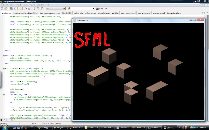
Looks good. Note from the screenshot, and from the SetPosition method of IsometricCamera, that this isn't a true isometric projection, but is in actuality the dimetric projection that results in a 2:1 tile ratio, as seen in games like Diablo. I like this projection, because it is easy to work with. And, of course, all of the assets for Goblinson Crusoe are rendered in this projection, so if I want to reuse them, I have to go with the same view.
Up next comes the difficult part. I need to figure out a rendering scheme that will render the scene, given that all of the pre-rendered assets (ground decals, objects, etc...) are rendered with anti-aliased, soft edges as described before. I need to figure out the shaders and lighting I'll need. This part might be a bit tricky, since I won't be using what you might call "standard" 3D lighting. Goblinson Crusoe implements a couple of things (fog of war, visibility-based lighting, negative lighting, and so forth) that seem like they'd be tricky to implement using "standard" models.
[page]
Constructing Geometry Using Anti-Aliased Sprites
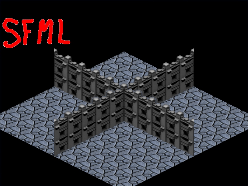
As a jumping off point for trying to use pre-existing anti-aliased rendered sprites, I want to create a few geometry primitives using some pre-rendered assets. For the first tests, I'll set up a set with a basic floor tile, a floor decal for decoration, a left wall, a right wall, a roof, and a basic wall decal for decoration. This will give me a good set to test with and, hopefully, help me to see where I'm going to have issues.
To begin, I'll just go ahead and grab the assets I made for the SFML isometric post.
Then I'll fire up Blender and map those sprites to some geometry. The way I do this for a 3D-based game is to create the geometry to match the shape and orientation of the sprite. I do need to construct the wall geometry to be of the proper height, in pixels, on the screen. This means taking into account the fore-shortening introduced by the camera angle.
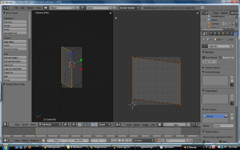
With a 2:1 tile-ratio dimetric projection, the camera angle above the horizon is 30 degrees, the angle around the Z axis is 45. Now, going with the above assets which are 64 pixels wide, this means that the total cell on-screen size is 128 pixels wide. Ignoring the 30 degree azimuth angle for a moment, we can calculate the length of the cube edges using the Pythagorean theorem, a^2+b^2=c^2. The hypotenuse is 128 pixels long, and the cube sides are the same length, so 2*a^2=128^2. Solving for a we get a=sqrt((128*128)/2) or a~90.5. So if the cube edges are approximately 90.5 in pixel units, then we now take into account the foreshortening of the vertical axis by the 30 degree azimuth angle, by multiplying the edge length by cos(30), to get approximately 78.384. Thus, taking the 64 pixel width of the isometric wall sprites, a unit cube on-screen will be approximately 78.384 pixels tall. We can prove this by firing up Blender and rendering a unit cube from the dimetric viewpoint to an image of the appropriate size:

If you open that image in an image editor and put the cursor at the apex of the near corner of the cube, you will see that it is approximately 78 pixels above the bottom of the image, so our math works. Now, the wall assets I created for the SFML isometric post are 256 pixels tall, and 64 pixels wide. The vertical axis represented is 224 pixels. Dividing 224 by 78.384 we get 2.8577. This is the amount we need to scale the unit cube by, vertically, in order to obtain geometry that matches the 64x256 size of the assets.
This stuff can get confusing, I know. One of these days I might try to write a more comprehensive guide, but for now I'm not too concerned about it. If we go back to Blender and apply the vertical scale to the unit cube, then re-adjust the output image dimensions to 128x256 (showing both the right wall and the left wall) and render, we'll get something like this:

You can see that this is the right size to get the full left and right walls. Now, since at this stage we are just trying to build geometry for the wall planes, we can go ahead and delete the "back" vertices of the cube:

This removes extraneous geometry and leaves us with just the wall planes. Now, we need to separate the planes into separate objects. We do this by entering edit mode, selecting the 4 vertices that form a wall plane, and hitting p to separate the selected pieces. This leaves us with 2 wall planes. The only thing left to do now is UV map them. Select a wall plane, enter edit mode and select all vertices, switch view to Camera view, press u to Unwrap, and select Project From View (Bounds). This will map the UVs from the camera view, and the result is something like this:
Do the same with the other wall piece. From here, it's a simple matter of applying materials to the wall pieces and exporting them to Collada for conversion, then loading them into the game framework to see the results. Here is a test run with the left wall piece:
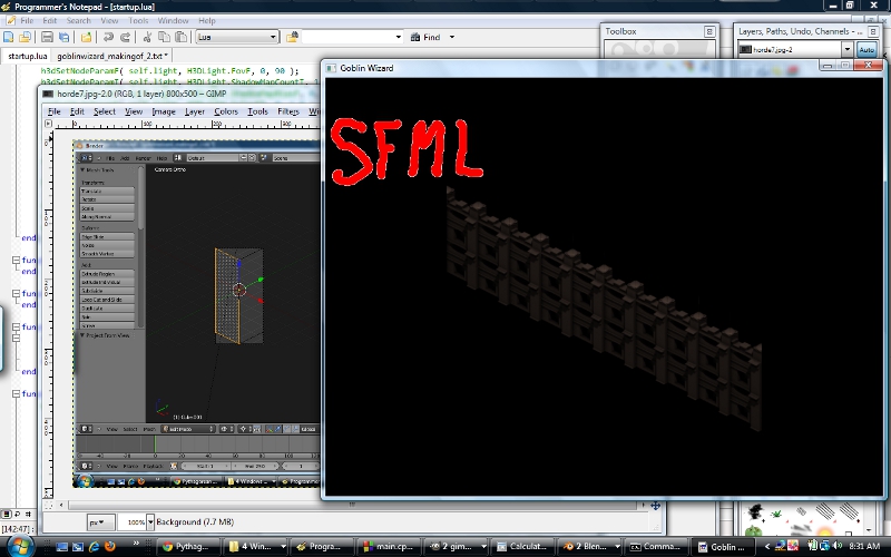
The image is scaled down so you can't really see it, but there are filtering artifacts due to small math imprecisions. I'm still using the default shaders. I'll be replacing them with more appropriate ones that will disable filtering to avoid those artifacts soon.
The floors, roofs, and floor/roof decal geometry setups are similar, though much easier to do. For those, I simply use a 1x1 plane oriented on X/Z.
Next up, I'm going to figure out a drawing order and re-write the basic shaders I'll be using.
[page]
Since we're not using the lighting model implemented in the sample shaders included with Horde3D, a lot of the stuff in our environment shaders can go away or be simplified. We also need to write the shaders so that alpha blending is performed. I have to dig into the docs a bit to figure this part out. After digging around for a little bit, I construct a first iteration of a pipeline and a shader. First, the shader:
[source]
[[FX]]
sampler2D albedoMap = sampler_state
{
Address=Clamp;
};
context SOLID
{
VertexShader = compile GLSL VS_GENERAL;
PixelShader = compile GLSL FS_GENERAL;
}
context TRANSLUCENT
{
VertexShader = compile GLSL VS_GENERAL;
PixelShader = compile GLSL FS_GENERAL;
BlendMode = Blend;
}
[[VS_GENERAL]]
#include "shaders/utilityLib/vertCommon.glsl"
uniform mat4 viewProjMat;
uniform vec3 viewerPos;
attribute vec3 vertPos;
attribute vec2 texCoords0;
varying vec4 pos, vsPos;
varying vec2 texCoords;
void main(void)
{
pos = calcWorldPos( vec4( vertPos, 1.0 ) );
texCoords = vec2( texCoords0.s, 1.0-texCoords0.t );
gl_Position = viewProjMat * pos;
}
[[FS_GENERAL]]
uniform sampler2D albedoMap;
varying vec4 pos, vsPos;
varying vec2 texCoords;
void main(void)
{
gl_FragColor = texture2D(albedoMap, texCoords);
}
[/source]
The shader is really very simple. I set the address mode of the texture sampler to Clamp, to avoid the filtering artifacts I got in the earlier render. Then I set up solid and translucent contexts. The vertex and fragment shaders for each context are the same, I merely change the BlendMode to Blend for translucent geometry. The shaders themselves are pretty much the most basic of texture-mapping shaders. The vertex shader transforms the coordinate, inverts the t component of the texture coords (or else the image will be upside down) and passes through the transformed vertex. The fragment shader merely passes on the texture sample. There is no lighting or other complex calculation going on.
Then, I put together a test pipeline:
[source]
[/source]
Here, I set up 4 stages of drawing. The Ground is drawn first, followed by any partially-transparent ground decals. Then walls, and finally wall decals. The stages beyond Ground have the order parameter set to "BACK_TO_FRONT" which, according to the pipeline documentation, should sort the geometry from back to front before drawing the given stage.
I then have to edit the materials for the assets to point to the new shader, and in the main application I load the new pipeline instead of the pipeline from the Horde3D samples. I also add a class attribute to the Material tag of each material, indicating its class, ie Ground, GroundDecal, Wall or WallDecal. Then I fire it up, build a real quick test level, and see what it looks like.
Uh oh. You see that stuff that's going on in the middle? Here, let me zoom in on it for you:
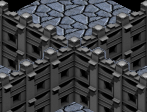
You remember what I said about certain pixels being assholes? You are seeing them, right now, deep in the midst of assholery. This is exactly what I was talking about.
What is going on here is that the geometry actually isn't being properly sorted. Some walls that are in front of others are being drawn first, so that when those behind walls are drawn, the depth values written by the front walls clip the pixels, resulting in "halo" behavior. This is exactly what isn't supposed to happen, if the geometry is properly rendered back-to-front. So either I have misunderstood the function of the order parameter in the pipeline DrawGeometry element, or the actual sorting isn't working correctly. So, I guess it's time to dig into Horde3D once more and see if I can figure out exactly what is going on.
This is the sort of problem that can lead one to just forego using nicely anti-aliased sprites, and accept a certain amount of "jagginess" in their environment graphics. If simple alpha-testing is used, with no partial transparency, then it doesn't matter if the geometry is sorted or not.
If I can't sort this out, it's not a deal-breaker. My hardware is atypically crappy these days, so I can safely assume that most players would have the ability to do some FSAA to smooth things out. However, the ouchie part would be re-rendering all of GC's assets to eliminate the anti-aliased edges. Perhaps I can just write a script tool to iterate the asset directories and manually process out the blending, rather than re-rendering everything.
Anyway, tune in next time as I see what results I get using non-anti-aliased sprites....


I've decided to sort blended objects in my project and only have blended objects when its really needed (windows, fires etc.). Though my sorting algorithm is rather crapy. I'll look forward to future posts.