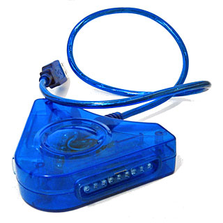
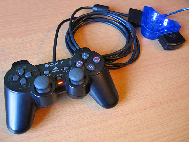
I recently purchased an inexpensive PlayStation controller USB adaptor for my PC. Several reviews confirmed that it was compatible with the controller's analogue joysticks so I thought it would be what I was after. Life is rarely that easy with cheap electronics, unfortunately!
When it arrived I plugged it in and Windows installed the appropriate HID drivers for it automatically, but as much as I waggled the joysticks on a connected DualShock 2 controller the axis preview in Control Panel remained resolutely in the zero position. PlayStation controllers have an "Analog" button that can be pressed to toggle between digital and analogue modes, but any attempts to press this resulted in the "Analog" light briefly flashing before immediately switching off again.
Thinking it may be a driver issue I tried to install the drivers from the mini CD that had been included with the adaptor. My PC could not read the disc (it appeared to be scratched, and was not very well protected in postage) so I hunted around online until I found a package that worked using the device's USB ID (VID_0810&PID_0001). This enabled the controller's rumble/vibration feature, but I still couldn't get analogue input to work. Thinking that if one driver package could add vibration support, another might add analogue support I contacted the Amazon seller to ask them if they could send me a copy of the correct drivers - they instead chose to send me a whole other unit in the post.
In the meantime, I experimented with another controller plugged into the adaptor. I was surprised to find that with two controllers plugged in at once I could enable analogue mode on one of the controllers. This made me think there could be a power issue - the second controller increased the capacitance across the power supply, which would make it more resilient to voltage spikes and reduce ripple that could be causing the controller to reset out of analogue mode. This was further confirmed by plugging the adaptor with a single controller into a powered USB hub - in this scenario the controller would only leave analogue mode when vibrating. I checked the power supply pins on the controller ports and was very surprised to see that there was apparently nothing connected to pin 5, which is supposed to deliver +5V to the controllers. At this point I decided to dismantle the adaptor to see what was going on.
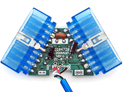
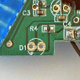
On the inside of the adaptor I could see that several components had been omitted. This could be to blame on cost-cutting measures (e.g. the LEDs D1 and D2 which are purely cosmetic) but the removal of D3 puzzled me the most - this diode is connected between USB VCC and the controller port pin 5, and is presumably responsible for providing power to the connected controller. I put this down to an oversight at the factory, and soldered a 1N4001 rectifier diode in the marked place.
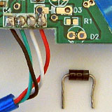
The above image shows a close-up of the place the missing diode should appear - D3 is indicated by a silk-screened diode symbol. Unsurprisingly the 1N4001 silicon diode has far superior characteristics to the silk-screen diode it replaced.
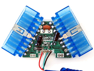
With the diode in place both controller ports started working flawlessly, even allowing me to use a wireless Guitar Hero controller receiver (though not the whammy bar - Guitar Hero controllers lack the "Analog" button to manually enable the analogue mode and instead rely on the PlayStation to enable it via software). Whilst I had the soldering iron out I thought I should add the missing LEDs, once again using the existing markings to establish the correct polarity:
If the markings are unclear, the anode (+) is always to the left when viewing the bottom of the circuit board when the other markings are upright.
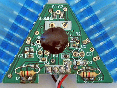
As the enclosure is blue and I seem to remember some fuss being made of the PlayStation 2's blue LED when it first came out I opted to use two blue LEDs with 1K5 resistors. I do not have any surface-mount resistors but through-hole ones fit quite easily though they can be a little fiddly to solder down.
When the replacement adaptor arrived in the post I was surprised to see that (once again) the diode D3 was missing and it demonstrated the same problems as the other one I'd fixed. I find it unlikely that the same mistake could be made twice, so this seems to be a genuine cost-cutting measure. Microcontroller I/O pins often have an internal protection diode between them and the positive power supply, which is how I assume the circuit works at all when the controllers are left unpowered - a small amount of current flows from the I/O (data) pins to the positive rail via these protection diodes, which is just enough to let the controller work in digital mode but once they draw more current (e.g. when sampling analogue inputs or driving the vibration motors) the voltage droops far enough for the controller to reset and leave analogue mode.
With these fixes in place I now have two working PlayStation USB adaptors for the price of one (and two 1N4001 diodes). I'm still rather perplexed by why there's such a blatent flaw in the hardware, but it is at least an easy fix which is why I've written it up. In summary: if your cheap PlayStation to USB adaptor ("Twin USB Vibration Gamepad", "Twin USB Joystick") is not working correctly, unscrew it and see if D3 is missing. If it is, solder a 1N4001 or similar diode between the two holes left for that purpose.


Nice read, I have the same adapter, but my PSOne joystikcs are working fine in analog mode, through D3 is missing