Edit: Along with other additions i've merged this tutorial with my stick topic.
I decided to do a quick tutorial on how to make your own normal map from scratch in Photoshop, only using the Nvidia normal map filter for "normalizing" our normal map.
Now, as i discussed before, a normal map is a texture/image which records lighting information. Lighting in 3d using per-pixel lighting is calculated using two vectors:
1.) The light source.
2.) The "normal", which is basically a vector accompanying a polygon.
Here, we have two vectors, the normal and the direction of the lighting source. Using these two points we can calculate the angle of the polygon in relation to the lighting source, and as such, the amount of light it should receive. When you model a high polygonal mesh, it looks nicer not only because the silhouette is more defined, but because the mesh itself contains more polygons and so more normals to calculate lighting, and as a result it looks more detailed. This is where normal mapping applies. Normal mapping, unlike the old bump mapping, actually adds normals to a model. So, where before one polygon= one normal, now with a normal map defining the normals, one polygon= theoretically as many normals as there are pixels in the map. In turn, this allows us low poly game modelers the ability to define very detailed lighting on our models, with our need only to have enough polygons (tris) to define the silhouette.
Generally the correct usage of a normal should be then to use it to hold the lighting detail, then to focus on modeling a correct silhouette for the mesh to hide as many signs that it is low poly as possible. What this will do is allow us to then trick the viewer into feeling the mesh they’re viewing is in fact high polygon. If they see the appropriate lighting detail that one would expect of a high polygon model, they will not question whether it is one or not, it is only the silhouette that then may give away the models true polygon count.
A few ways to generate a normal map:
1.) Image generated – type 1 – Here an artist may paint the normal map by hand as a grayscale heightmap. White representing the highest extrusion possible, black representing the lowest point of extrusion. Here various levels of gray then represent various levels of height. This map is then passed through a normal map filter, where this information is used to calculate lighting detail based on the raw extrusion information from the grayscale map. The most common image generated normal mapping applications are, Crazybump, and the Nvidia Photoshop normal mapping filter. Both have their uses, but I’d recommend Crazybump for most instances.
2.) Image generated – type 2 – Here, as we will be exploring later, an artist can hand make a normal map, only using a normal map filter to “normalize” the map.
3.) 3d generated – Here an artist will model a high or low polygon model, in an attempt to then generate a normal map from it, either for an unwrapped mesh or for a tillable texture. Generally speaking, 3d generated normal maps tend to look the best, as they are generated straight from the geometry they’re made to imitate. However, it will be a skill that must be gained by the artist to judge when to take the time to do a 3d generate normal map or simply use an image generated one. It is harmful to one’s workflow to rely too much on either. Sometimes an image generated normal map will look exactly the same as a 3d generated one, other times the difference will be glaringly obvious. To make the best use of your time, choose wisely.
Developing Your Model for Normal Mapping:
As I stated earlier, the silhouette is the key, to be able to effectively trick the viewer you must not allow the silhouette to give it away. A few rules to follow for this:
1.) As you model, rotate the mesh to view it from different angles, here you’ll want to look for any “chunkiness” or sharp edges/points that do not define the models true shape. Unless you poly budget is extremely tight, consider adding a cut or two to help smooth out the area. Remember, in this day and age of per-pixel lighting and shaders, Fill-Rate is a bigger performance enemy than a few extra polygons. Generally you can add a few extra polygons and get no decrease in rendering rate (within reason of course).
2.) Add trimming to almost everything! If your normal map is doing an excellent job of faking depth in your brick texture, why ruin it for the viewer/player by having that illusion dashed the second they get to the end of the wall and see it becomes harsh and flat. Trimming helps maintain this illusion by having the viewer feel that the brick has not abruptly ended.
Now, on to the point of this tutorial. With all of the methods for creating and using normal maps, it is imperative to truly understand them at a technical level and so be able to edit them at their technical level.
Some background on how a normal map works –
A normal map is composed on 3 color channels, the standard RGB, each of these channels in your standard 24 bit texture is then 8 bits (8x3=24). So, what does an 8 bit image give us? It allows us 256 levels of gray to use, per channel. So, each channel is only a grayscale image made up of 256 levels, but when pulled together they then define a full color image. Here, you have something similar to a heightmap, except instead of extrusion, different values bring forth different intensities of that particular channel color. Full white in a channel will be 100% of that color, black will be 100% absence of that color, and values in between are color intensities in between. This is important to know, because a normal map holds its information inside each channel.
Each color channel has its own purpose to a normal map. From the perspective of facing the normal map, your red channel holds the lighting information of left/right. The green channel holds the lighting information of up/down. And the blue channel holds the direct lighting information, that is, the lighting of the normal map at no angle, hence why a normal map is almost always largely made of blue. Or alternatively you can think of the red channel as holding the horizontal lighting information and the green holding the vertical lighting information.
Quick Tutorial
You will need the Nvidia Photoshop Normal Map plugin for this tutorial. Get it
Here
Steps:
1.) In photoshop (or any other image editor that gives advanced access to channels), go to file -> New:
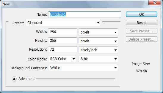
Use the options i have in the screenshot
2.) Double click on your foreground color box on the left, under the rgb color number, change them all to 128, this will produce neutral gray.
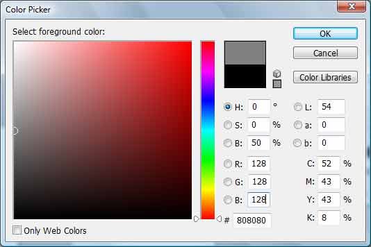
Like above
3.) Fill your 256x256 image with the nuetral gray.
4.) Now change your forground color to 174 for all rgb numbers.
5.) Select your text tool, click on your image and type whatever you want, as long as it fits in the image.
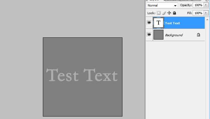
Like above
6.) Right click on your text layer and duplicate it.
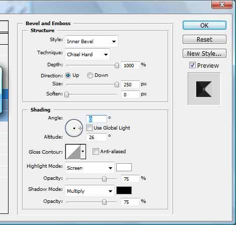
7.) Deactivate all layers except for your first text layer, double click on it to add a layer effect, select emboss and use the settings i've applied here:
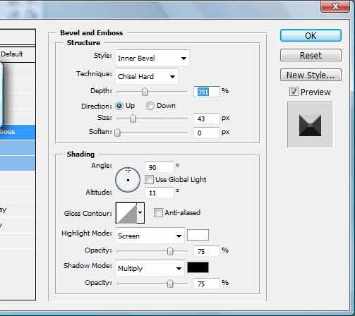
Then Click "Ok"
8.) Add a new blank layer, and with this new layer active and the first text layer active only, hit Ctrl+Shift+E (Mac, CMD+Shift+E). This will merge only the layers you have visible together, effectively rasterizing the layer effect we just created (If anyone knows an easier technique please share).
9.) Now with only your second text layer visible/active (the one we made by duplicating the first text layer), go and apply emboss to it, just like the last one, except use these settings:
Click "Ok"
10.) Now, once again, create a new blank layer, and with your new blank layer and your second text layer only, merge visible (Ctrl+Shift+E). Now select the resulting layer by pressing Ctrl+A (to select all) and copy it by pressing Ctrl+C.
11.) Make all of your layers visible and select your main layer (the one that contains the 128 neutral gray). Now its time to be introduced to the color channels. Right beside the layer tab is often by default the color channels tab, simply click on that tab to see the channels. Here all of the rgb channels can be individually selected (simply click on one of the channels to only have it active). For our purposes, simply click on the red channel.
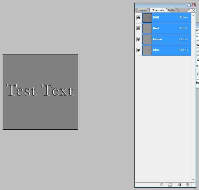
12.) With the red channel select, and only the red channel (meaning, only the red channel will be activated), press Ctrl+V to paste the layer we just copied into it. As i mentioned above, the red channel is responsible for the left/right or horizontal lighting information, hence that we're pasting the text that has the left/right embossing on it into this layer. The shading that is left/right corresponds to how the lighting will be affected when used as a normal map.
13.) Under the channels tab still click on the "RGB" channel at the top, this will reselect all of your channels automatically. Next we're going to select the first text layer, the one that had the up/down emboss applied to it. Once again hit Ctrl+A, then Ctrl+C.
14.) Again, select your main layer (the one with the 128 neutral gray), go to the channels tab, but this time select only the green channel and hit Ctrl+V. Then Hit Ctrl+D to deselect the selection that is automatically created.
15.) Now click on the blue channel, with only the blue channel selected, hit D, then hit X. This will cause your foreground colors to go back to Default, then pressing X will switch your foreground to white. Now fill in the blue channel with 100% white.
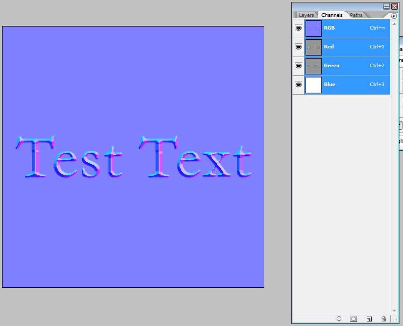
16.) Now, hit the "RGB" channel again to make sure you have all channels selected, go to your layers tab. Throw away your text layers keeping only your main layer. Now your channels tab should look something like below, and your image will start to look very similar to a normal map!
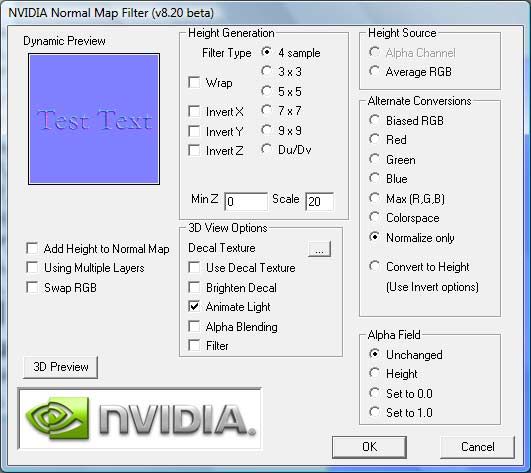
17.) Now, our normal map is not quite finished yet. You see, as i said earlier, a normal is a vector sticking out of a polygon. A normal map produces a single vector, which adds up to one by mixing the different color channels together. So say you have your lighting at an extreme angle, the normal map will be creating a normal which is in between the data it reads from the red channel and the green channel. This vector still adds up to one. If you don't understand this then don't worry about the details, just always understand that any changes to a normal maps color will require a normal map to need to be "Renormalized" again to make each vector add up to one. To do this, startup the Nvidia photoshop filter i mentioned earlier, Filters -> Nvidia Tools -> NormalMapFilter.
Select the settings i have below. Notice i have it set on "Normalize Only."
18.) You'll see your normal map change color slightly. Save your normal map to your format of choice. But remember! Avoid lossy formats when you're saving normal maps. Jpeg or any lossy compression ruins the lighting data/information held in a normal map.
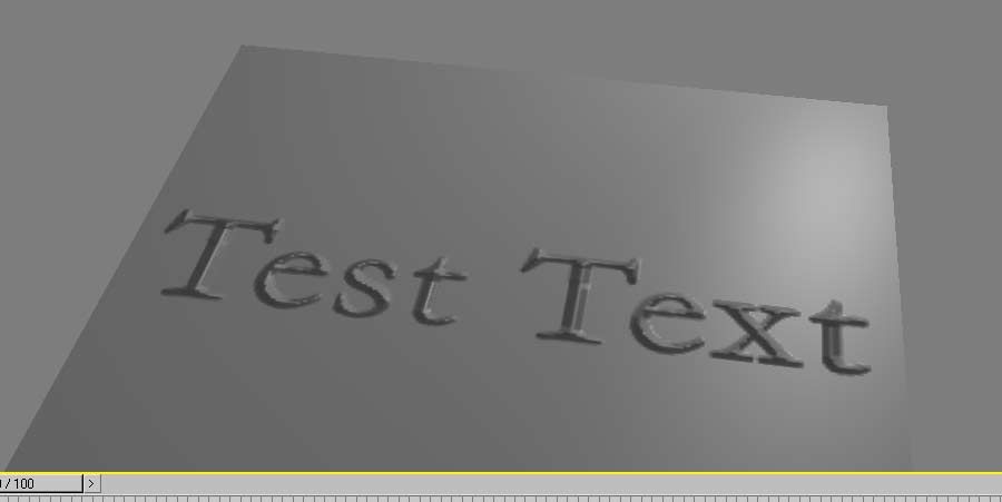
Now you're finished! To see your work loadup your normal map into your favorite normal map preview utility, the screenshot below is from 3ds Max using a custom FX shader using a DX9 material.
Now, the reason for doing all of this is for us to explore how a normal map functions and therefore how best to edit one. You'll find that as you use normal maps more and more, you'll need the skill to edit them by hand. Failing to do so will limit you. Not to mention, understanding normal mapping in general will allow you to better use it.
I hope you find this tutorial helpful.
Jarrod
[Edited by - Jarrod1937 on March 5, 2008 6:45:34 PM]
-------------------------Only a fool claims himself an expert