This is a post which describes what me and my partners did for a graphics programming final and how to do it. Hopefully, someone will find this information useful and implement it and/or improve upon it.
--------------------------------------------------------------------------------
I recently took a class in 3D graphics where we could choose our final project to be whatever we wanted. My partner and I chose to attempt to create rainbows and other spectral phenomena within a ray tracer. We chose this because this is typically not possible with standard ray tracing techniques and it would be fun to do the "impossible". Most modern ray tracers are backwards casting (Tracing rays from the eye/camera into the scene) whereas the real world is forward casting (casting light rays from a light source into a scene). This is because it is magnitudes of order more efficient to figure out what the eye can see rather than tracing every possible photon. There are some limitations to backward casting ray tracers: ray tracing rainbows and light passing through a prism becomes difficult. We managed to solve this problem by doing a combination of forward and backward ray casting in a two pass renderer.
The first pass renders the light as it interacts with geometries and then stores the interaction details for a point. The second pass is from the camera into the scene which figures out what is visible and figures out how to shade it. This requires a bit of rethinking in the way ray tracers model the world, so before I get into that, a quick review on the science behind light would be helpful.
-Light is emitted from a light source and behaves as both a particle and a wave.
-You can reference a specific band of light either by its wavelength or frequency.
-Visible light ranges from 380 nanometers to about 850nm, which goes from ultraviolet to infrared, respectively.
-Each wavelength represents a particular color in the visible spectrum.
-White light consists of every color in the visible spectrum, so it would be represented by the sum of all wavelengths.
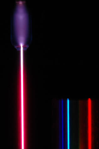
-Not all light sources are white light. Helium, hydrogen, argon, neon, sodium, (etc.) gasses all emit different bands of light when they are energized.
-You can't tell which wavelengths are present in a light source merely by looking at the composite color. You'd need to use a spectral diffractor of some sort to see all of the component wavelengths of a light source.
Converting Wavelengths into RGB values
Usually, color is represented as a triple of Red, Green and Blue values (RGB) for monitor displays. Unfortunately, there is not a 1:1 relationship between RGB values and the physical color spectrum. If you diffract white light into its components and compare it to the RGB color spectrum, you'll notice that some colors in the RGB spectrum are missing from the visible light spectrum (Most noticeably, turquoise). In 1931, the International Commission on Illumination (CIE) came up with a specification derived from empirical testing by a 'standard observer' which matches RGB values to light wavelengths.
If you'd like to learn more about the science behind color, the wikipedia article is a good starting place:
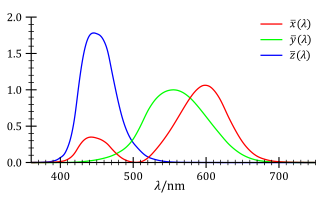
CIE 1931 color space
In our project, we initially started with the 2-degree CIE 1931 color space but were unhappy with how poorly the red was being emphasized. The red wasn't showing up very prominently because the graph of the green values was very close to the values of the red. We decided to be a bit unscientific and used a hybrid of the 1931 CIE values and the green values from the 1959 Stiles & Burch results. The green values in the Stiles & Burch are shifted to the left which makes red more distinct. We found freely available data sets of the XYZ RGB values in a CSV format and parsed the results into our application. Most results are for wavelengths in multiples of five, so we simply interpolate results for non-multiples.
Light Source Representation
Usually light colors are represented as RGB values. If we're trying to diffract light into its component colors, we'll need to represent light as wavelengths instead. We created a new type of light source which is a point light which shoots out a single ray in a given direction. For lack of a better name, I called it "beam". In our ray tracer, we use an XML file to describe objects in our scene, such as geometries, materials, lights, camera, etc. Here is a rough schematic of how our light structure looks:
<light>
<type>beam</type>
<position>0 0 -10</position>
<direction>0 0 1</direction>
<wavelengths>380 850</wavelengths>
</light>
The wavelength parameter consists of pairs of numbers which determine the range of a particular band of color. If you wanted white light, you'd specify a pair of numbers starting at the ultraviolet wavelength (~380) and ending at the infrared wavelength (~850). If you wanted to describe something like a hydrogen light source, you'd specify the start and end positions for each wavelength in that particular spectrum (available online). A single color would be represented with the start and stop values being the same (this becomes important later).
General Implementation concept:
So, we created a scene which has several beam light sources pointing towards a geometry (our screen to project onto). Near the light positions, we created two transparent angled planes which represent a glass prism. From the light source, we shoot a ray in the given direction and find the closest intersection. If the closest intersection has any transparency and also has a refractive index other than 1.0, we figure out how to refract the light according to
Snell's Law of refraction and
Sellmeiers equation which computes refraction angles for each wavelength. It's important to note that
every wavelength of light refracts at a slightly different angle which is why we see a gradient of colors in rainbows and light passing through a prism. After we determine that a beam of light impacts a surface requiring refraction and have computed all of the new refracted directions, given the wavelengths, we recursively create a new light beam for each wavelength and repeat until we impact a surface which has no transparency. At this point, we know the end position of the light beam ray(s) and the wavelength(s) of the light beam. Not caring much for efficiency, I just created a linked list of Vector3's which store the hit position in the scene followed by the color. Now the forward ray casting has been completed.
In the backward casting pass, for each point in the scene, I compare its distance to every point listed in the linked list of colors. Since the hit positions are of very high floating point precision, 99.99% of light ray impact positions will not match eye ray positions, so I assign a delta value of around 0.05f. If a camera ray is within this distance to the light beam end position, I grab the color value and add it to the existing shader values.
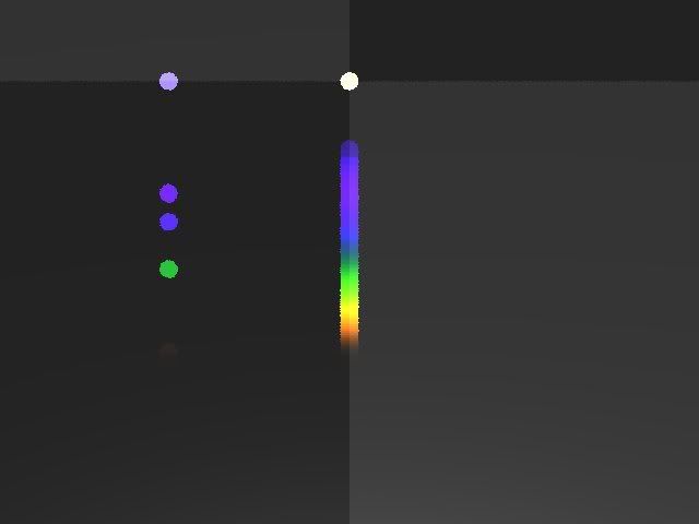
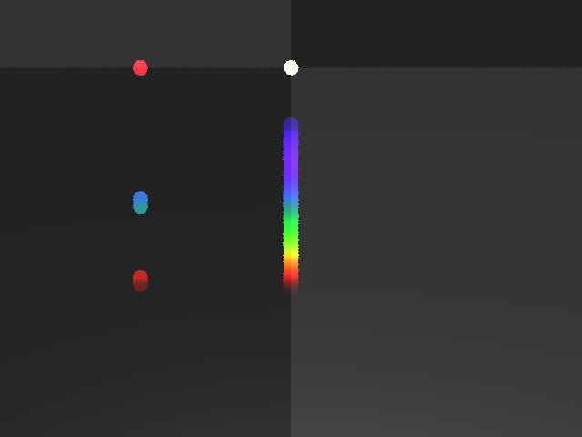
Results:
You're looking at two images. The first one is using the CIE 1931 standard for color. The second one uses my hybrid between the CIE 1931 standard and the Stiles & Burch standard (just did a green shift). In both images, the data set is (roughly) the same. There are four lights in the scene. The lights on the left hand side are supposed to represent a "hydrogen" light. The top portion shows the composite light, the bottom portion shows the composite light being diffracted through a prism. The right hand side represents a white light and the diffraction of its component colors below. In the Stiles & Burch image, I was trying to more accurately model the representation of hydrogen light by emphasizing the light band intensities and eye ball matching the band colors.
 Possible Improvements:
-Performance: A better data structure could be used to search for the light beam hit positions. Perhaps even a more thought out approach?
-Light intensity: Scientifically speaking, certain light sources have some color bands which have a higher intensity of brightness which impact the overall color output. My model currently assumes that the intensity is uniform across every band.
-A method for eliminating the forward casting altogether? I'm not entirely sure how this would be implemented but I suspect this is very possible -- maybe even preferable.
Thanks for reading. If any of this is confusing or you have questions, let me know.