Need help with 3D Tiled Terrain w/texture atlas

Started by
12 comments, last by Zoa 13 years, 9 months ago
I am reversing the game assets out of my favorite game, because I wanted to learn game programming. I choose this route because it is 100 times more impressive when you get something working when you start with quality art. Although the quality art thing might be debatable, it is way better than I could do.

Anyways I got the height map, normals, vertex shade, and tile number figured out, but I can't for the life of me get the specific tile to show up on my terrain. I read all kinds of great articles, but still don't quiet understand the pixel shaders. I am having trouble in the pixel shader which specifies the particular pixel and associating that with the coordinate of the specific tile texture I wish to lay down.

Can anyone help me out, or point me in the right direction for placing a specific texture/tile (stored in a larger texture) on my terrain mesh. Also, for the texture coordinates that get passed in to the pixel shader, I am presuming these are the coordinates in the texture that are associated with that particular pixel? If the tiles are specified at the vertex level, or associated with 4 vertices that will change in the up coming tile (and are shared among up to 8 other tiles), how do you assign the texture corrdinates? Also, how do you tell the pixel shader what tile to use? I am so confused on this subject, I hope I am asking the right question.


Below are the specifics on what I have so far. Sorry so long, but I wanted to include as much info as possible without including irrelevant items...

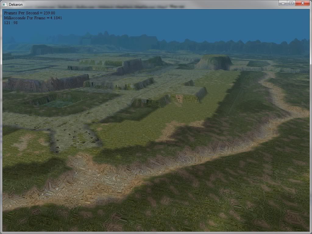
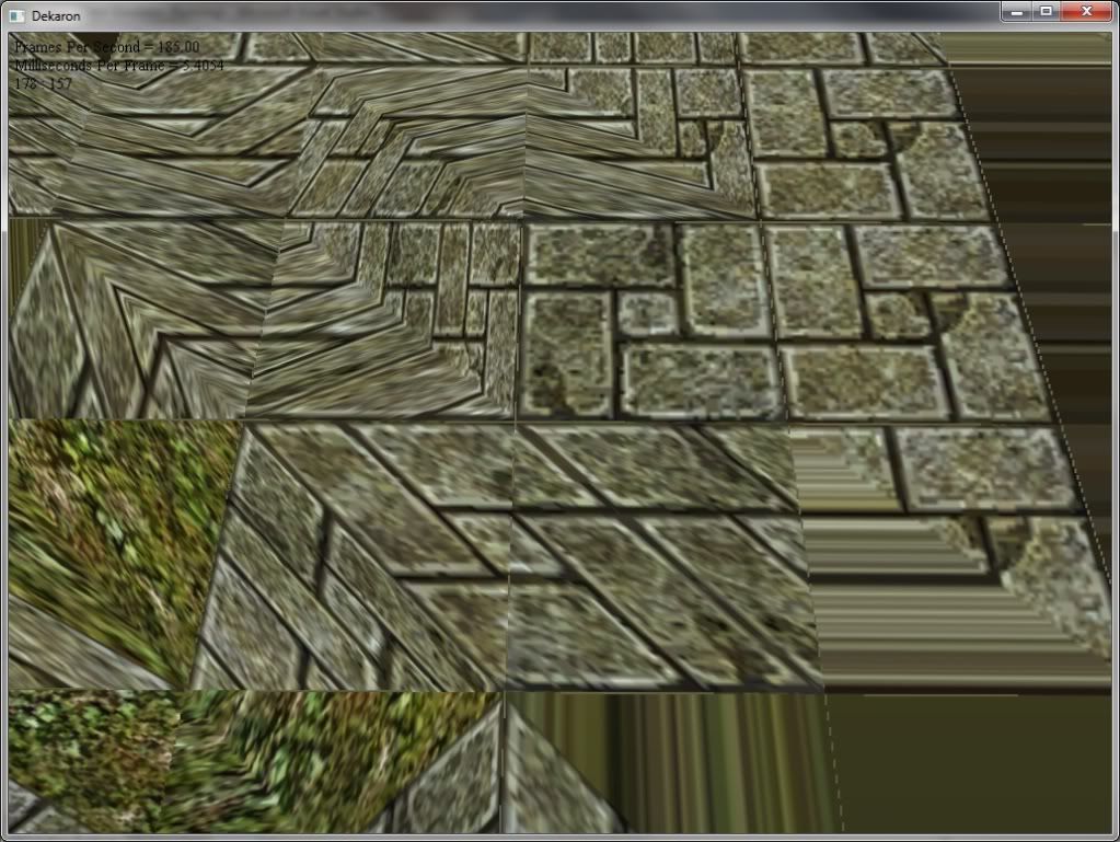
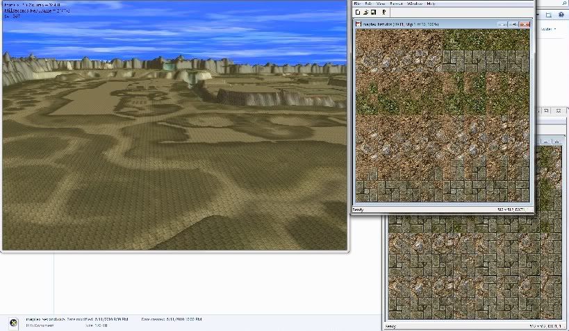
Here is a picture of what I have rendered so far. It is a generic texture for now. Height maps are done, along with normal lighting, and vertex shading. Off to the right side are the 2 textures that are going to be used for the tiles. There are 128 tiles total.

Picture of Braiken map and map tiles

The ground mesh is 513 by 513 and right now all the verticies are shared. I have seen some people use separate verticies for each tile, but I do not want to increase the number of verticies unless I absolutely have to. Eventually I will split these into 33x33 pieces to do some quick culling.

Below is how the mesh is being created
	// Build vertices.	// We are working on X first as if they were rows, then Z would be the colums.	// The reason behind this is because the map files are oriented this way.	m_GroundVertices.resize(m_NumGroundVertices);	int k = 0;	for(int i = 0; i < m_SizeOfZ; ++i)	{		for(int j = 0; j < m_SizeOfX; ++j)		{			m_GroundVertices[k].x = j * m_SpaceBetweenXCells;			m_GroundVertices[k].y = m_pMapFile->GetMapInfo()->pMapVertex[k].pos.y;			m_GroundVertices[k].z = i * m_SpaceBetweenZCells;						++k; // Next vertex		}	}	// Build indices.	m_GroundIndices.resize(m_NumGroundTriangles * 3);	 	// Generate indices for each quad.	k = 0;	for(int i = 0; i < numZCells; ++i)	{		for(int j = 0; j < numXCells; ++j)		{			//      b ---- c			//       |   /|			//       |  / |			//  ^    | /  |			//  |    |/   |			//  z+  a ---- d			//  y is up			//  x+ ->						DWORD a =  (i      * m_SizeOfX) +  j;			DWORD b = ((i + 1) * m_SizeOfX) +  j;			DWORD c = ((i + 1) * m_SizeOfX) + (j + 1);			DWORD d =  (i      * m_SizeOfX) + (j + 1);			m_GroundIndices[k]     = a;			m_GroundIndices[k + 1] = b;			m_GroundIndices[k + 2] = c;								m_GroundIndices[k + 3] = a;			m_GroundIndices[k + 4] = c;			m_GroundIndices[k + 5] = d;			// next quad			k += 6;		}	}


Below is the vertex buffer. Right now for the texture coordinates I am just wraping the tile over and over.
for(int i = 0; i < m_SizeOfX; ++i){  for(int j = 0; j < m_SizeOfZ; ++j)  {    DWORD index = i * m_SizeOfX + j;    v[index].pos = m_GroundVertices[index];    v[index].normal = m_pMapFile->GetMapInfo()->pMapVertex[index].normal;    v[index].tex0 = D3DXVECTOR2((float)i, (float)j) * texScale;    v[index].col = m_pMapFile->GetMapInfo()->pMapVertex[index].col;  }}// Also the index buffer for completnessfor(DWORD i = 0; i < m_NumGroundTriangles * 3; ++i){  k = (DWORD)m_GroundIndices;}


Below is the VS and PS
uniform extern float4x4 gWorld;uniform extern float4x4 gWorldInvTrans;uniform extern float4x4 gWVP;uniform extern float4 gAmbientMtrl;uniform extern float4 gAmbientLight;//uniform extern float4 gDiffuseMtrl;uniform extern float4 gDiffuseLight;uniform extern float4 gSpecularMtrl;uniform extern float4 gSpecularLight;uniform extern float  gSpecularPower;uniform extern float3 gLightVecW;uniform extern float3 gEyePosW;uniform extern texture gTex;sampler TexS = sampler_state{	Texture = <gTex>;	MinFilter = Anisotropic;	MagFilter = LINEAR;	MipFilter = LINEAR;	MaxAnisotropy = 8;	AddressU  = WRAP;  	AddressV  = WRAP;}; struct OutputVS{    float4 posH    : POSITION0;    float4 diffuse : COLOR0;    float4 spec    : COLOR1;    float2 tex0    : TEXCOORD0;};OutputVS DirLightTexVS(float3 posL : POSITION0, float3 normalL : NORMAL0, float2 tex0: TEXCOORD0, float4 c : COLOR0){    // Zero out our output.	OutputVS outVS = (OutputVS)0;		// Transform normal to world space.	float3 normalW = mul(float4(normalL, 0.0f), gWorldInvTrans).xyz;	normalW = normalize(normalW);		// Transform vertex position to world space.	float3 posW  = mul(float4(posL, 1.0f), gWorld).xyz;		//=======================================================	// Compute the color: Equation 10.3.		// Compute the vector from the vertex to the eye position.	float3 toEye = normalize(gEyePosW - posW);		// Compute the reflection vector.	float3 r = reflect(-gLightVecW, normalW);		// Determine how much (if any) specular light makes it into the eye.	float t  = pow(max(dot(r, toEye), 0.0f), gSpecularPower);		// Determine the diffuse light intensity that strikes the vertex.	float s = max(dot(gLightVecW, normalW), 0.0f);		// Compute the ambient, diffuse and specular terms separatly. 	float3 spec = t*(gSpecularMtrl*gSpecularLight).rgb;//float3 diffuse = s*(gDiffuseMtrl*gDiffuseLight).rgb;	float3 diffuse = s*(c*gDiffuseLight).rgb;	float3 ambient = gAmbientMtrl*gAmbientLight;		// Sum all the terms together and copy over the diffuse alpha.	outVS.diffuse.rgb = ambient + diffuse;//outVS.diffuse.a   = gDiffuseMtrl.a;	outVS.diffuse.a   = c.a;	outVS.spec = float4(spec, 0.0f);	//=======================================================		// Transform to homogeneous clip space.	outVS.posH = mul(float4(posL, 1.0f), gWVP);		// Pass on texture coordinates to be interpolated in rasterization.	outVS.tex0 = tex0;		// Done--return the output.    return outVS;}float4 DirLightTexPS(float4 c : COLOR0, float4 spec : COLOR1, float2 tex0 : TEXCOORD0) : COLOR{	float3 texColor = tex2D(TexS, tex0).rgb;	float3 diffuse = c.rgb * texColor;    return float4(diffuse + spec.rgb, c.a); }technique DirLightTexTech{    pass P0    {        // Specify the vertex and pixel shader associated with this pass.        vertexShader = compile vs_2_0 DirLightTexVS();        pixelShader  = compile ps_2_0 DirLightTexPS();	// Specify the render/device states associated with this pass.	//FillMode = Wireframe;    }}


Vertex format
//===============================================================struct VertexPNTC{	VertexPNTC()		:pos(0.0f, 0.0f, 0.0f),		normal(0.0f, 0.0f, 0.0f),		tex0(0.0f, 0.0f),		col(0x00000000){}	VertexPNTC(float x, float y, float z, 		float nx, float ny, float nz,		float u, float v,		D3DCOLOR c):pos(x,y,z), normal(nx,ny,nz), tex0(u,v), col(c){}	VertexPNTC(const D3DXVECTOR3& v, const D3DXVECTOR3& n, const D3DXVECTOR2& uv, D3DCOLOR c)		:pos(v), normal(n), tex0(uv), col(c){}	D3DXVECTOR3 pos;	D3DXVECTOR3 normal;	D3DXVECTOR2 tex0;	D3DCOLOR    col;	static IDirect3DVertexDeclaration9* Decl;};


Thanks ahead to anyone who can direct me on what I need to do in the pixel shader to get the individual tiles down on the mesh. Also, I am going to guess that the way I need to specify the initial texture coordinates needs to change.

[Edited by - Zoa on June 27, 2010 12:46:14 AM]
Advertisement
Very creative!!!! If you want to make a 3D tile terrain game you should start with a cross-screen game like sonic the hedgehog. That will tell you the basics of tile terrain.
I downloaded and fired up 2Moons, is this the game you got the artwork from?

If so, that game's terrain is using something called "terrain splatting", not tiling.

Look for a 2-d grid of layer and blend map file names. This will form a "splat stack" for each patch of terrain. If there are 8x8 patches that form the entire terrain, there will be 64 splat stacks, each stack will reference a list of filenames that are mapped to the layer and blend maps. The same layer map texture will be used on many different terrain patches' splat stacks, but there will likely be a different blend map for each terrain patches' splat stack.

You will need to generate two sets of texture coordinates in your vertex shader, one tiled across the entire terrain patch (layer texcoords) and the other stretched to fit the whole terrain (blend map texcoords) patch.

In each of the 3 channels of the blend map texture is the amount of one of 3 (or 4) layer maps to combine using inverse src alpha as shown below.

Here's a vertex/pixel shader for one patch of Dark Age of Camelot's terrain. It supports 12 layer maps and 4 blend maps. The blend maps only use (r,g,b) channels.

uniform extern int      gPatchRow;uniform extern int      gPatchCol;uniform extern float4x4 gViewProj;uniform extern float4x4 gWorld;uniform extern float3   gDirToSunW;uniform extern float3   gEyePosW;uniform extern texture  gDetailMap;uniform extern texture  gSplatTex0;uniform extern texture  gSplatTex1;uniform extern texture  gSplatTex2;uniform extern texture  gSplatTex3;uniform extern texture  gSplatTex4;uniform extern texture  gSplatTex5;uniform extern texture  gSplatTex6;uniform extern texture  gSplatTex7;uniform extern texture  gSplatTex8;uniform extern texture  gSplatTex9;uniform extern texture  gSplatTex10;uniform extern texture  gSplatTex11;uniform extern texture  gBlendMap0;uniform extern texture  gBlendMap1;uniform extern texture  gBlendMap2;uniform extern texture  gBlendMap3;uniform extern float    g_hasBlend[ 4 ];uniform extern float    g_hasSplat[ 12 ];uniform extern float    gTexScale[ 12 ]; uniform extern float    gFogRange;uniform extern Mtrl     gMtrl;uniform extern DirLight gLight;uniform extern float4 gFogColor = {0.55f, 0.66f, 0.85f, 1.0f};static float  gFogStart = 1.0f;struct DAOCSplatOutputVS{    float4 posH         : POSITION0;    float2 tiledTexC    : TEXCOORD0;    float2 nonTiledTexC : TEXCOORD1;    float  shade        : TEXCOORD2;          float  fogLerpParam : TEXCOORD3;};DAOCSplatOutputVS DAOCSplatTerrainVS( float3 posW    : POSITION0,                                      float2 tex0    : TEXCOORD0,                                      float1 height  : TEXCOORD1,                                      float3 normalW : NORMAL0,                                      uniform int patchRow,                                      uniform int patchCol                                     ){    // Zero out our output.    DAOCSplatOutputVS outVS = (DAOCSplatOutputVS)0;    //	// Just compute a grayscale diffuse and ambient lighting	// term: terrain has no specular reflectance.  The color	// comes from the texture.	//	outVS.shade = max(dot(-gLight.dirW, normalW), 0.0f);        // Fiddle with the vertex position    float4 posT = mul(float4(posW, 1.0f), gWorld);    posT.y += height;    	// Transform to homogeneous clip space.	outVS.posH = mul(posT, gViewProj);		// Pass on texture coordinates to be interpolated in rasterization.	outVS.nonTiledTexC = tex0; // Blend map not tiled.	tex0.x = (tex0.x * (1.0f / 8.0f)) + (patchRow / 8.0f);	tex0.y = (tex0.y * (1.0f / 8.0f)) + (patchCol / 8.0f);	outVS.tiledTexC    = tex0; // Scale tex-coord to tile.		// Compute vertex distance from camera in world space for fog calculation.	float dist = distance(float3(posT.xyz), gEyePosW);	outVS.fogLerpParam = saturate((dist - gFogStart) / gFogRange);		// Done--return the output.    return outVS;}float4 DAOCSplatTerrainPS12( float2 tiledTexC    : TEXCOORD0,                              float2 nonTiledTexC : TEXCOORD1,                             float shade         : TEXCOORD2,                             float fogLerpParam  : TEXCOORD3) : COLOR{    //	// Layer maps are scaled and tiled.	//    float3 c0  = tex2D(SplatTex0S,  tiledTexC * gTexScale[ 0 ]).rgb;    float3 c1  = tex2D(SplatTex1S,  tiledTexC * gTexScale[ 1 ]).rgb * g_hasSplat[ 1 ];    float3 c2  = tex2D(SplatTex2S,  tiledTexC * gTexScale[ 2 ]).rgb * g_hasSplat[ 2 ];    float3 c3  = tex2D(SplatTex3S,  tiledTexC * gTexScale[ 3 ]).rgb * g_hasSplat[ 3 ];    float3 c4  = tex2D(SplatTex4S,  tiledTexC * gTexScale[ 4 ]).rgb * g_hasSplat[ 4 ];    float3 c5  = tex2D(SplatTex5S,  tiledTexC * gTexScale[ 5 ]).rgb * g_hasSplat[ 5 ];    float3 c6  = tex2D(SplatTex6S,  tiledTexC * gTexScale[ 6 ]).rgb * g_hasSplat[ 6 ];    float3 c7  = tex2D(SplatTex7S,  tiledTexC * gTexScale[ 7 ]).rgb * g_hasSplat[ 7 ];    float3 c8  = tex2D(SplatTex8S,  tiledTexC * gTexScale[ 8 ]).rgb * g_hasSplat[ 8 ];    float3 c9  = tex2D(SplatTex9S,  tiledTexC * gTexScale[ 9 ]).rgb * g_hasSplat[ 9 ];    float3 c10 = tex2D(SplatTex10S, tiledTexC * gTexScale[ 10 ]).rgb * g_hasSplat[ 10 ];    float3 c11 = tex2D(SplatTex11S, tiledTexC * gTexScale[ 11 ]).rgb * g_hasSplat[ 11 ];        //    // Blendmaps are not scaled or tiled.    //    float3 B0 = tex2D(BlendMap0S, nonTiledTexC).rgb;    float3 B1 = (tex2D(BlendMap1S, nonTiledTexC).rgb) * g_hasBlend[ 1 ];    float3 B2 = (tex2D(BlendMap2S, nonTiledTexC).rgb) * g_hasBlend[ 2 ];    float3 B3 = (tex2D(BlendMap3S, nonTiledTexC).rgb) * g_hasBlend[ 3 ];    	//	// INVSRC ALPHA blend + fog + light	//	float3 color = (c0);	       color = (B0.g * c1) + (1 - B0.g) * color;	       color = (B0.b * c2) + (1 - B0.b) * color;	       color = (B1.r * c3) + (1 - B1.r) * color;	       color = (B1.g * c4) + (1 - B1.g) * color;	       color = (B1.b * c5) + (1 - B1.b) * color;	       	       color = (B2.r * c6) + (1 - B2.r) * color;	       color = (B2.g * c7) + (1 - B2.g) * color;	       color = (B2.b * c8) + (1 - B2.b) * color;	       color = (B3.r * c9) + (1 - B3.r) * color;	       color = (B3.g * c10) + (1 - B3.g) * color;	       color = (B3.b * c11) + (1 - B3.b) * color;	       color *= shade;	           return (lerp(float4(color, 1.0f), gFogColor, fogLerpParam));}technique DAOCSplatTech{    pass P0    {        //////////////////////////////////////////////////        VertexShader     = compile vs_2_0 DAOCSplatTerrainVS( gPatchRow, gPatchCol );        PixelShader      = compile ps_2_0 DAOCSplatTerrainPS12();        //////////////////////////////////////////////////        CullMode         = CCW;        //////////////////////////////////////////////////		StencilEnable    = false;        AlphaBlendEnable = false;        AlphaTestEnable  = false;		ZWriteEnable     = true;        //////////////////////////////////////////////////		ZFunc            = Less;        SrcBlend         = SrcAlpha;		DestBlend        = InvSrcAlpha;        AlphaRef         = 0x0000005A;        AlphaFunc        = Greater;        //////////////////////////////////////////////////    }}


Example:

Terrain Splatting

P.S. It may be that 2Moons stores all their unique layer maps in those tile arrays you showed rather than in separate files... try to find the blend maps for the castle level.

Hope this helps!

[Edited by - Steve_Segreto on June 26, 2010 5:45:12 AM]
Yes it is 2moons/Dekaron.
The info that I found in the map file was a number that was 0-3 which references 1 of the first 4 groups (there are 4 textures to a group), then there was another number 0-3 which specified which tile to pick within that group. I found this out by loading up a private server and messing with the numbers. Now my guess was that depending on which tiles were next to the current tile, it would pick the correct tile (computed and choose from the 128 possible).

I have read up on texture splatting, but will read some more to wrap my head around how I can get this to work for me. Thanks for the info!

[Edited by - Zoa on June 27, 2010 12:57:35 AM]
... I looked into texture splatting, and although I could use it on this, I decided it was to much hassle to splat 16 textures, so I went back to texture atlas method. I got it kind of working, but I still can't get the texture coordinates right. If anyone can pin point what is going on, I would greatly appreciate it. I am so close, I can taste victory.

Here is a zoomed out view of what I have. The paths and grass areas a visible, but half of the triangles have stratched textures.
Map photo

Here is a close up of the ground. Note that some of the tiles are ok and others have half of the triangles streached.
Map photo - Close up

My verticies and incies have not been touched (see first post), but here is what I changed.
uniform extern float4x4 gWorld;uniform extern float4x4 gWorldInvTrans;uniform extern float4x4 gWVP;uniform extern float4 gAmbientMtrl;uniform extern float4 gAmbientLight;//uniform extern float4 gDiffuseMtrl;uniform extern float4 gDiffuseLight;uniform extern float4 gSpecularMtrl;uniform extern float4 gSpecularLight;uniform extern float  gSpecularPower;uniform extern float3 gLightVecW;uniform extern float3 gEyePosW;uniform extern texture gTex;static float3 gFogColor = {0.19f, 0.42f, 0.57f};static float gFogStart = 30.0f;static float gFogRange = 513.0f;sampler TexS = sampler_state{	Texture = <gTex>;	MinFilter = Anisotropic;	MagFilter = LINEAR;	MipFilter = LINEAR;	MaxAnisotropy = 8;	AddressU  = WRAP;  	AddressV  = WRAP;};struct InputVS{	float3 position : POSITION0;	float3 normal : NORMAL0;	float4 shade : COLOR0;	float2 tex0: TEXCOORD0; 	float2 tex1: TEXCOORD1;}; struct OutputVS{	float4 posH    : POSITION0;	float4 diffuse : COLOR0;	//float4 spec    : COLOR1;	float2 tex0    : TEXCOORD0;	float2 tex1    : TEXCOORD1;	float fogLerpParam : TEXCOORD2;};OutputVS DirLightTexVS(InputVS inVS){    // Zero out our output.	OutputVS outVS = (OutputVS)0;		// Transform normal to world space.	float3 normalW = mul(float4(inVS.normal, 0.0f), gWorldInvTrans).xyz;	normalW = normalize(normalW);		// Transform vertex position to world space.	float3 posW  = mul(float4(inVS.position, 1.0f), gWorld).xyz;		//=======================================================	// Compute the color: Equation 10.3.		// Compute the vector from the vertex to the eye position.	float3 toEye = normalize(gEyePosW - posW);		// Compute the reflection vector.//float3 r = reflect(-gLightVecW, normalW);		// Determine how much (if any) specular light makes it into the eye.//float t  = pow(max(dot(r, toEye), 0.0f), gSpecularPower);		// Determine the diffuse light intensity that strikes the vertex.	float s = max(dot(gLightVecW, normalW), 0.0f);		// Compute the ambient, diffuse and specular terms separatly. //float3 spec = t*(gSpecularMtrl*gSpecularLight).rgb;//float3 diffuse = s*(gDiffuseMtrl*gDiffuseLight).rgb;	float3 diffuse = s * (inVS.shade * gDiffuseLight).rgb;	float3 ambient = gAmbientMtrl * gAmbientLight;		// Sum all the terms together and copy over the diffuse alpha.	outVS.diffuse.rgb = ambient + diffuse;//outVS.diffuse.a   = gDiffuseMtrl.a;	outVS.diffuse.a   = inVS.shade.a;//outVS.spec = float4(spec, 0.0f);	//=======================================================		// Transform to homogeneous clip space.	outVS.posH = mul(float4(inVS.position, 1.0f), gWVP);		// Pass on texture coordinates to be interpolated in rasterization.	outVS.tex0 = inVS.tex0;	outVS.tex1 = inVS.tex1;	// Compute vertex distance from camera in world space for fog calculation.	float dist = distance(inVS.position, gEyePosW);	outVS.fogLerpParam = saturate((dist - gFogStart) / gFogRange);		// Done--return the output.    return outVS;}float4 DirLightTexPS(float4 c : COLOR0, float2 tex0 : TEXCOORD0, float2 tileCoord : TEXCOORD1, float fogLerpParam : TEXCOORD2) : COLOR{	//float2 tileCoord;	//tileCoord.x = 7;	//tileCoord.y = 7;	// Texture is 8 x 8	tex0.x = (frac(tex0.x) / 8) + tileCoord.x / 8;	tex0.y = (frac(tex0.y) / 8) + tileCoord.y / 8;//float3 texColor = tex2D(TexS, outVS.tex0).rgb;	float3 texColor = tex2D(TexS, tex0);	float3 diffuse = c.rgb * texColor.rgb;    // Add fog.//float3 final = lerp(diffuse + spec.rgb, gFogColor, fogLerpParam);float3 final = lerp(diffuse, gFogColor, fogLerpParam);    return float4(final, c.a); }technique DirLightTexTech{    pass P0    {        // Specify the vertex and pixel shader associated with this pass.        vertexShader = compile vs_2_0 DirLightTexVS();        pixelShader  = compile ps_2_0 DirLightTexPS();	// Specify the render/device states associated with this pass.	//FillMode = Wireframe;    }}


Specifically here is how I am translating the pixel texture coordinates.

tex0.x = (frac(tex0.x) / 8) + tileCoord.x / 8;
tex0.y = (frac(tex0.y) / 8) + tileCoord.y / 8;

I am taking the original coordinates and getting just the decimal portion. Since I originally was using wrapping, all the texture coordinates were straight integers (0,0), (1,1), ... (513,513). Then I divide this number by 8 since my tiled texture has 8 x 8 texture in it. I then have another set of texture corrdinates that specify which tile to use in the texture. (0,0) would be the first tile, (1,0) would be the second tile, (0,1) would be the 9th tile (first one in the second row).

For now I am just using the first 16 tiles. I will work on computing the blend tiles later.

So my problem is, that my texture coordinates are getting messed up, and I can't figure out why. Since I am testing the individual pixel and striping off the decimal why are the coordinates bleeding over from other tiles (from what it looks like).
Why don't you tell me how you unpacked the pack files for this game and I'll help you get your terrain splatting done?

Even when you get the approach you are working on to "work", it won't be visually correct because you will still have a hard edge between a grass quad and a road quad.

You are just trying to get one quad (two triangles) to get textured using a specific rectangle of a larger texture, you need to specify the correct row, col offset into the larger texture in the vertex shader and let the GPU interpolate the u,v coordinates across the faces of the two triangles in the pixel shader (i.e. don't mess with the texture coordinates in the pixel shader).

But this will never give you more than one terrain type on a particular quad though, without a blend map you cannot get soft transitions between quads or even have a quad that shows more than one kind of terrain at once (unless they have a lot of hand-made blended tiles that is?)

Anyway here's what I suggest:

You want the texcoords in your vertex buffer to range from 0.0f to 1.0falong each quad (consider the 3x3 grid below, it has 9 quads with 18triangles and 16 vertices (if you share vertices)). The key here isyou can't share vertices and get this to work, so you need to duplicatevertices and have 24 vertices in this example not 16.Now, you can have u coordinates that range from 0.0f to 1.0f betweenvertex 00 and vertex 01 and v coordinates that range from 0.0f to 1.0fbetween vertex 00 and vertex 06, as well as u coordinates that rangefrom 0.0f to 1.0f between vertex 02 and vertex 03.When u = 0.0f it is the same as (0,0) in the texture atlas and whenu = 1.0f it is the same as (0, TILE_WIDTH-1) in the texture atlas.Likewise for v, but using TILE_HEIGHT-1 instead./*Terrain mesh:                    Texture Atlas (4 tiles),                                 6 x 4 pixels each0.0   1.0 0.0    1.0                  0.0  0.5   1.0 ==> u00=====01,02=====03,04=====05          aaaaaabbbbbb|        |         |        |       |  aaaaaabbbbbb |        |         |        |       |  aaaaaabbbbbb06=====07,08=====09,10=====11       v  aaaaaabbbbbb|        |         |        |      0.5 ccccccdddddd|        |         |        |          ccccccdddddd12=====13,14=====15,16=====17          ccccccdddddd  |        |         |        |      1.0 ccccccdddddd|        |         |        |18=====19,20=====21,22=====23 */int numVertRows = 4;int numVertCols = 4;for (int i = 0; i < numVertRows; i++){    for (int j = 0; j < numVertCols; j++)    {        D3DXVECTOR2 tex0;        tex0.x = ( i % 2 == 0 ) ? 0.0f : 1.0f;        tex0.y = ( j % 2 == 0 ) ? 0.0f : 1.0f;    }}To get all the quads to display tile 'a' (the 0,0 tile) in thetexture atlas, do this in the vertex shader:#define TILE_WIDTH    (6) // in pixels#define TILE_HEIGHT   (4) // in pixels#define NUM_TILE_ROWS (2)#define NUM_TILE_COLS (2)outTexCoord.u = inTexCoord.u * (TILE_WIDTH / (NUM_TILE_COLS * TILE_WIDTH));outTexCoord.v = inTexCoord.v * (TILE_HEIGHT / (NUM_TILE_ROWS * TILE_HEIGHT));Remember the incoming texture coordinates are either 0.0 or 1.0, sothis will give you either 0.0 * (6 / 12) = 0.0 or 1.0 * (6 / 12) = 0.5for each vertices 'u' coordinate. By passing this out to the pixel shaderthe GPU will interpolate all the values between 0.0 and 0.5 for you.Simply sample the larger texture atlas using these u,v coordinates andyou will fill all your quads with the (0,0) tile image (the 'a' in theabove atlas).To allow you to specify a different tile image per quad, you will needto augment the vertex declaration with an additional texture coordinatethat just stores the (x,y) of which tile you want to use. Assuming thisis called inTileCoord, the outTexCoord computations become this:outTexCoord.u = inTexCoord.u * (TILE_WIDTH / (NUM_TILE_COLS * TILE_WIDTH));outTexCoord.v = inTexCoord.v * (TILE_HEIGHT / (NUM_TILE_ROWS * TILE_HEIGHT));outTexCoord.u += inTileCoord.u * (TILE_WIDTH / (NUM_TILE_COLS * TILE_WIDTH));outTexCoord.v += inTileCoord.v * (TILE_HEIGHT / (NUM_TILE_ROWS * TILE_HEIGHT));So to get the 1,1 quad of the terrain (the middle one) to render usingthe 'c' tile in the texture atlas do this...1. In C++ fill the inTileCoord of vertices 8, 9, 14, and 15 with thevalues { 0.0, 1.0 } before sending to the vertex shader.2. Ensure that vertices 8 and 14 have u,v, coordinates of (0, 0) andvertices 9 and 15 have u,v coordinates of (1, 1).3. In the vertex shader the output texture coordinates for vertex 8would be:u = 0 + 0 * (6 / (2 * 6)) = 0.0v = 0 + 1 * (6 / (2 * 6)) = 0.5and the output texture coordinates for vertex 15 would be:u = (1 * (6 / (2 * 6))) + (0 * (6 / (2 * 6))) = 0.5v = 0.5 + 1 * (6 / (2 * 6)) = 1.0As you can see this would fill the middle quad with the 'c' tile ofthe texture atlas...(0.0, 0.5) - (0.5, 1.0)


[Edited by - Steve_Segreto on June 27, 2010 2:12:38 AM]
Also i have a feeling that because all of the vertexs are shared he is ending up overwriting the uv cords of a given vertex cause his texturing issues, some vertexes will have the correct tile info on them only by pretty much random chance
the memory foot print of your terrain model will be small compared to the textures in your atlas, you are only looking at an incress in terrain size of 4x, and almost any semi modern video card will rock that in its sleep
0))))))>|FritzMar>
Bump - edited
Hey, I am also using a texture atlas with my terrain rendering and here is what I think your problem is:

Because you are using indexed (shared) vertices, you are not only sharing the position of vertices between tiles, but also the texture coordinates. This will result in the sort of artefacts you are seeing as a texture coordinate that might be correct on a vertex for one tile, may be completely wrong for the adjacent tile.

Unfortunately, if you want to use a texture atlas, I think you will not be able to use indexed vertices, unless you can find some fancy way of using multiple texture coordinate sets to fix this issue. My suggestion would be to either ditch the texture atlas, or ditch index vertices. The later will probably be the best option for what you are trying to achieve. Obviously this will increase the number of vertices you create.
I think what you've done is very very good. I'll be really happy if I can get similar results when I come to it myself. If you don't mind I'd like to copy your code, print it off and study it in advance of when I tackle this myself. Looks really good to me, with the exception of the few small problems you're having with it, but I can;t really notice them to be honest.

This topic is closed to new replies.

Advertisement