handling UV discontinuities

Started by
16 comments, last by mrbastard 12 years, 4 months ago
I'm working on a demo which computes the mandelbrot set in an HLSL pixel shader. I've been getting some great effects by using an 'orbit trap' and using the resulting values as texture coordinates.

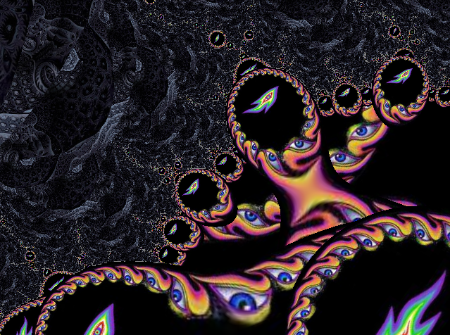
The problem is that where the texture coordinates change very quickly between pixels I get horrid artifacts. See the thin, broken purple lines in the image below.

colour.png
Ignore the texture magnification blur in the middle bottom of the image - it's just a low res texture!

Here's an image of the UVs, ( u in red, v in green, blue=0 ) - hopefully that points out where the artifacts would occur, even if you can't immediately see them in the first image tongue.gif
UVs.png


Now, some of you are probably already reaching for a link to docs on sampleGrad. I've tried playing with it, but so far have only managed to bias the problem one way or the other - one side or other of the round features is still 'bad'. I may not fully understand what I'm doing though, and I'd be very grateful for an explanation if anyone thinks this is the right route to go down.

Another possible solution which I'm working on is to render the UVs to a texture and smooth them out with a box filter. I'll lose detail in the UV map, but I don't think that will make much difference to the final image.

I've also tried just painting over the artefacts - as they occur at the very edge of the 'trapping circle' I guessed they would fall between ~0.99 and 1.0. It turns out that the artefacts are actually on pixels next to (but sufficiently different in UV value from) the pixels with values 0.9...1.0. This is what led me to believe I couldn't solve this with knowledge of only one pixel - I need to use ddx/ddy/sampleGrad or another pass.

Any suggestions?
[size="1"]
Advertisement
It looks like it's just a filtering artifact. If you sample with linear filtering then the texture units will end fetching adjacent texels and using them in the filtering, which can be bad for cases like yours where the UV's have discontinuities. However in your case it appears as though you only have artifacts when sampling at the very edges of your texture (which makes sense), which means you should be able to use CLAMP or BORDER filtering mode to avoid bringing in texels from an unrelated part of the texture.
When texture coordinates change very quickly from one pixel to the next, the hardware will assume that it needs to sample a low-resolution mip-map. The quickest way to hack around this behaviour is to disable mip-mapping, either on your texture (by not supplying mips), by setting max-lod to 0 on your sampler, or using SampleLevel to force it to use LOD 0.

The same artefacts occur in deferred shading when using projected light textures, or "cookies"/"gobos", but I can't remember the common work-arounds off the top of my head, besides disabling mipmapping altogether as above...

That effect looks awesome BTW, especially with the Alex Grey artwork.
Thanks MJP.

I'd already wondered if it was the texture addressing mode, but to be sure I tested again. Both CLAMP and BORDER give much the same result. Here's BORDER:
colour_border.png


Just in case though, here's my setup code:
sampDesc.Filter = D3D11_FILTER_MIN_MAG_MIP_LINEAR;
sampDesc.AddressU = D3D11_TEXTURE_ADDRESS_BORDER;
sampDesc.AddressV = D3D11_TEXTURE_ADDRESS_BORDER;
sampDesc.AddressW = D3D11_TEXTURE_ADDRESS_BORDER;
sampDesc.ComparisonFunc = D3D11_COMPARISON_NEVER;
sampDesc.MinLOD = 0;
sampDesc.MaxLOD = D3D11_FLOAT32_MAX;


There are other parts of the image, outside of the area in the shots, where the UVs become > 1.0 and wrap without artifacts. The artifacts only appear when neighbouring pixels have wildly different UVs. I've tried detecting these big shifts using ddx and ddy, but so far I either miss a lot of the artifacts or get a lot of false positives.
[size="1"]

When texture coordinates change very quickly from one pixel to the next, the hardware will assume that it needs to sample a low-resolution mip-map. The quickest way to hack around this behaviour is to either disable mip-mapping on your texture, or use SampleLevel to force it to use LOD 0.

Brilliant, thanks. SampleLevel 0 clears it up a treat. I really do need the mipmapping though - lots of magnification and minification zooming around a fractal. See the minification sparklies:
SampleLevel.png


I'll see if I can get any further using ddx and ddy to select pixels where I want to set the mip level. I started reading a few articles on how this kind of stuff is handled in deferred rendering when I first found out about SampleGrad - I'll have to do some more!


That effect looks awesome BTW, especially with the Alex Grey artwork.


Thanks! It looks even better in motion. Funnily enough, when I went looking for textures to try out with fractal trapping, Alex Grey was my first thought. Well, maybe after M.C. Escher biggrin.gif I'd like to have a go at reproducing some of Grey's designs procedurally - maybe the flame and ring in the images above. Hopefully he'd approve!

I'm not sure whether to leave the images and music in the finished demo and just stick it on youtube, or to attempt something of my own so I can let people download the whole thing and interact with it.
[size="1"]

The same artefacts occur in deferred shading when using projected light textures, or "cookies"/"gobos", but I can't remember the common work-arounds off the top of my head, besides disabling mipmapping altogether as above...


The usual way to do it is to just derive a mip level using some metric other than UV gradients (for instance, something based on the depth of the pixel).
I don't know if you can do it easily and cheaply, but maybe you can examine the texture coordinates of adjacent pixels and choose a mip level according to how close or far to each other they are.
If you compute the maximum difference between the U or V coordinate of your fragment and the corresponding coordinate of each adjacent pixel, it translates directly to the ideal texture size for that pixel; then you can use trilinear interpolation to mix the two closest mip levels.

Omae Wa Mou Shindeiru


I don't know if you can do it easily and cheaply, but maybe you can examine the texture coordinates of adjacent pixels and choose a mip level according to how close or far to each other they are.
If you compute the maximum difference between the U or V coordinate of your fragment and the corresponding coordinate of each adjacent pixel, it translates directly to the ideal texture size for that pixel; then you can use trilinear interpolation to mix the two closest mip levels.


Thanks. I could certainly do that in an extra pass - I'd rather avoid doing the actual mandelbrot function more than once per pixel.

I'm not sure I follow your reasoning about the ideal texture size, but I'm in a rush in my lunch break. I'll have some time this evening and will give it a try.

Thanks again

[size="1"]
You don't need an extra pass, the derivatives of any value can be calculated in a pixel shader using ddx and ddy. You could use those to detect discontinuities, and clamp your gradients to a smaller value to prevent going down to a smaller mip level.
I agree with Hodgman - the effect looks fantastic. Lateralus is one of my favorite albums.... I would love to see a video of this in action! Great work!

This topic is closed to new replies.

Advertisement