Matrix transformation to move camera without respect to pitch or roll

Started by
5 comments, last by haegarr 12 years, 4 months ago
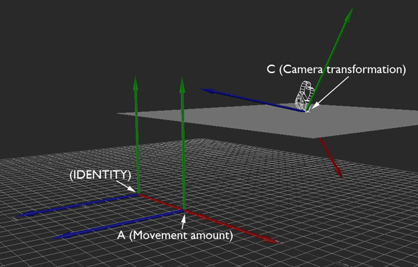
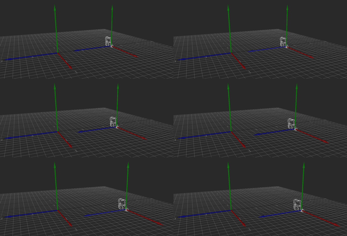
Some setup: I'm working in a Y-up coordinate system where X is forward. I have an object that I'm trying to move. To give you some context, I'm moving a camera with standard first-person joystick controls. If I tilt the joystick forward, I want the camera to move forward.

aamove1.gif

Ordinarily, this movement is local to the camera. If I push the stick such that I want to move 128 units forward and 64 to the right, the camera moves by 128 units along its forward (X) vector and by 64 along its right (Z) vector.
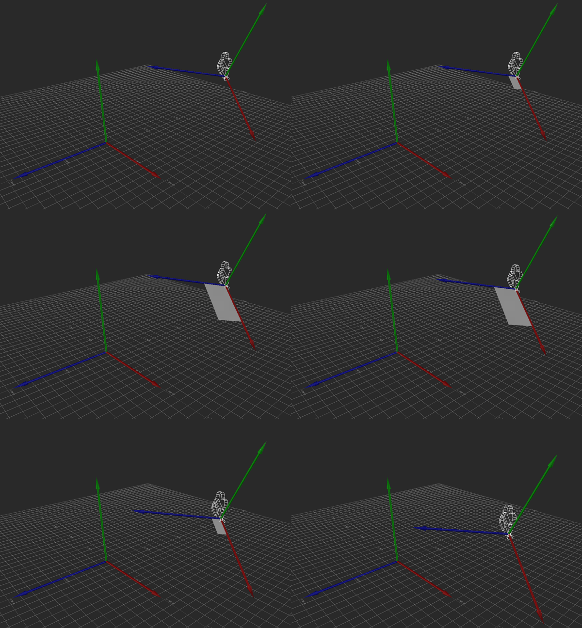
aamove2.gif

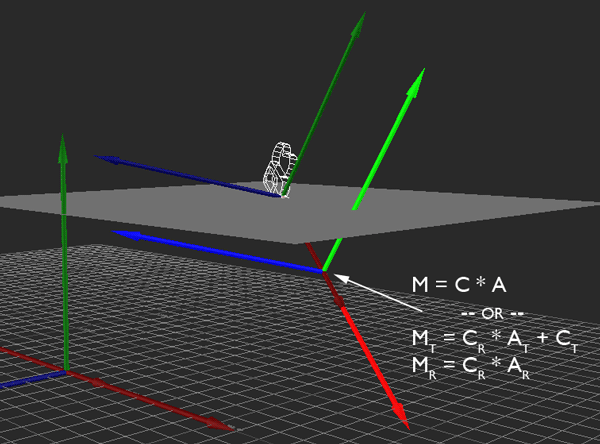
I'm performing this transformation with some simple matrix multiplication. I simply multiply the camera's transformation matrix C by the desired movement A to get the new camera position. This is all fine and dandy, and because I'm using matrices, this covers me for whatever translation, rotation, and scale the camera might have.
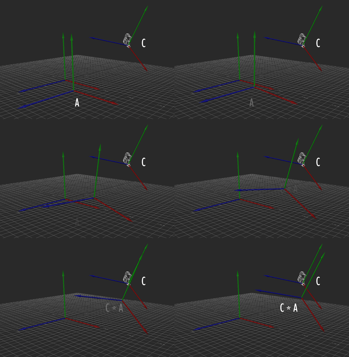
aamove3.gif

So in local movement mode, that's how the desired change in position, as indicated by joystick input, is interpreted and applied as camera movement.

However, I also want there to be another mode for camera movement, and this is where I need some help. In this mode, moving forward-back or right-left does so without respect to pitch or roll (i.e., parallel to the ground (XZ), without changing altitude (Y)), and moving up-down does so in the direction of global Y (straight up and down, without respect to rotation). However, I still want to preserve the original heading of the camera, so that it's still moving forward, in some sense.
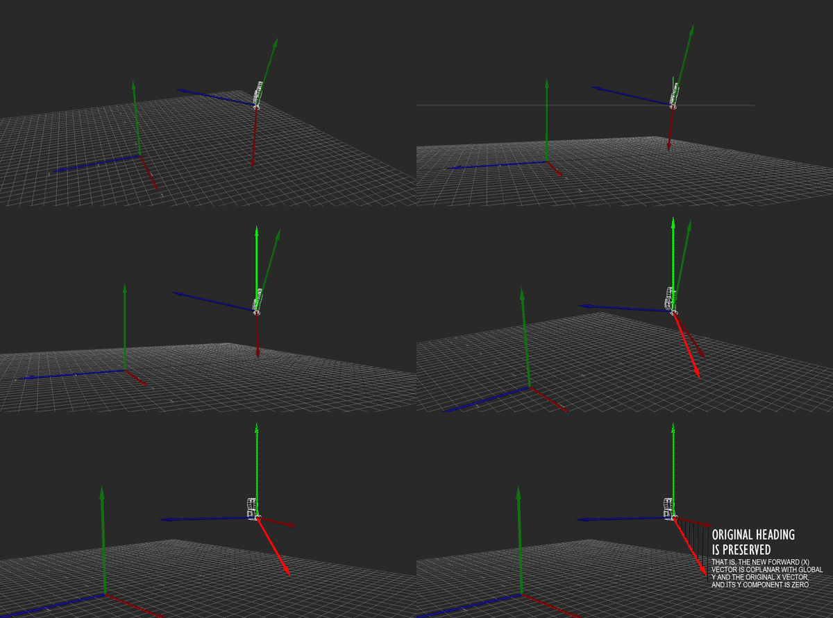
aamove4.gif

Hopefully the above image explains it (If it happens to be stopped, you may need to reload it). Conceptually, what I want to do is rotate the camera so that its local Y axis is aligned with global Y, its local X and Z are parallel to the ground (global XZ), and its yaw (i.e., its rotation about the Y axis) matches the heading it originally had. That way, I can apply the movement just as before, then restore the original rotation.
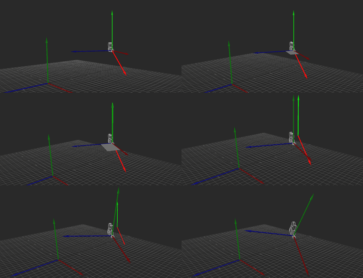
aamove5.gif

Unfortunately, I'm profoundly uneducated when it comes to matrix math. I can think of a few ways to achieve what I'm looking for (using cross products to construct the new transformation matrix, directly altering Y position after local-space movement is calculated), but I haven't come up with a solution that meets all the criteria I need and also fits neatly into the whole transformation matrix paradigm. If you can think of one, I would dearly love to hear it.

Thanks!
Advertisement
Just multiply vector by rotation matrix.
For example if you need to move camera 10 units up (0, 10, 0), take camera's rotation matrix (lets say it's rotated 30 degrees around z axis), apply transformation to vector and it'll become around (5, 8.66, 0), then add it to camera's position, and you should get what you need (if I understood your question correctly).
From your videos (BTW, I've never seen before such an effort made to explain us a given problem :) it seems me that you use column vectors, and so do I in the following.

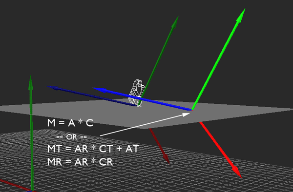
If you have a matrix C that relates the camera to the world, and you apply another transformation A on the global side of the matrix (i.e. the left side if using column vectors)
M := A * C
then A is applied w.r.t. the world. Splitting M into a translational and a rotational part
M[sub]T[/sub] = A[sub]R[/sub] * C[sub]T[/sub] + A[sub]T[/sub]
M[sub]R[/sub] = A[sub]R[/sub] * C[sub]R[/sub]
one can see that A[sub]T[/sub] isn't influenced by C.

Until now you have applied A on the local side of C, because you have computed (another M here)
M := C * A
Again splitting M into a translational and a rotational part

M[sub]T[/sub] = C[sub]R[/sub] * A[sub]T[/sub] + C[sub]T[/sub]
M[sub]R[/sub] = C[sub]R[/sub] * A[sub]R[/sub]
one can see that A[sub]T[/sub] is "rotated" by C[sub]R[/sub].

Add on: If you want to apply a local transformation on the global side, you first have to ensure that the spaces are the same, i.e. you have to transform the global space to be coincident with the local one, then apply the transformation, and then undo the first transformation. In summary you yield in the already known
( C * M * C[sup]-1[/sup] ) * C = C * M
I really appreciate your thorough explanation. I went through it line-by-line, and it's certainly enlightening, but I'm not sure if it addresses my question. If you can bear with me, I'd like to take a look at your math as it applies to my examples so we can see whether I'm missing something.

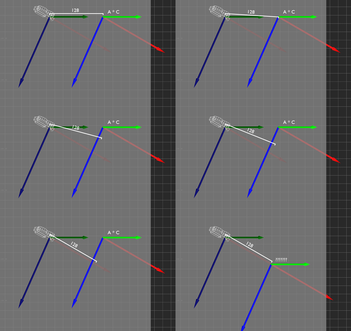
Here's the setup. In this case, A is simply moving forward by 128 units.

aamove6.gif

From what I can tell, the M values that you split into translation and rotation matrices have the same effect as the multiplication of the translation matrices of C and A. (I think you meant that, as you're simply breaking down the transformation in order to explain it, but I could be wrong).

Here's your second M, which is the local transformation, or C * A:

aamove7.gif

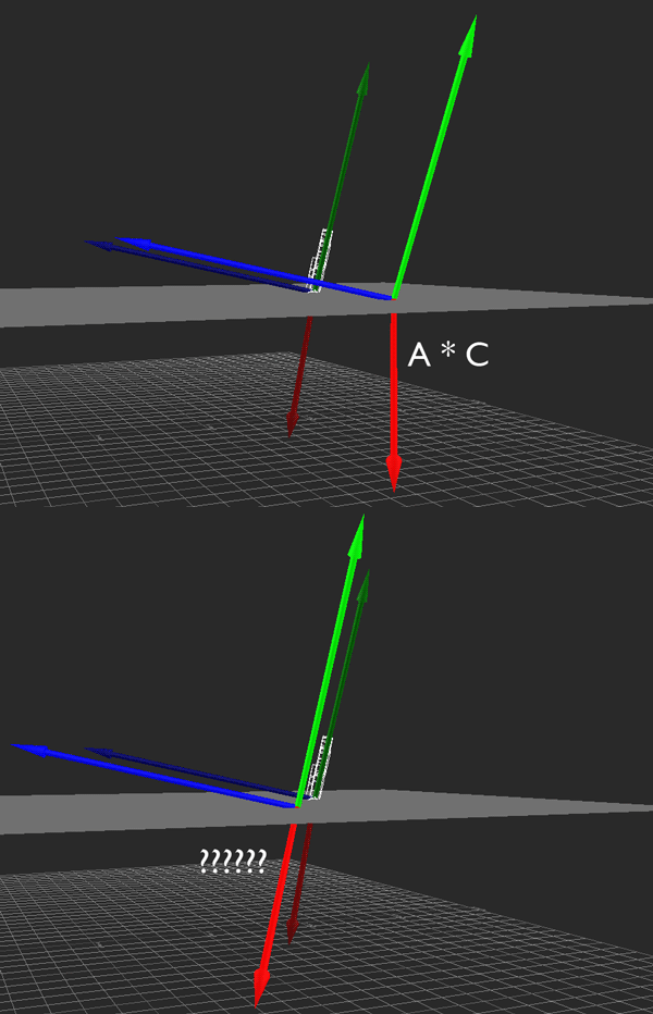
Here's the first M, which is the global transformation, or A * C:

aamove8.gif

This is all great, but what I'm looking for is a little of both. The global example is good, except that for the translation, I want "forward" to indicate the original heading of the camera instead of simply being global X, but still lying parallel to the ground. To look at this in a top view:

aamove9.gif

That difference, in a perspective view, showing that Y position is unaffected:

aamove10.gif

Basically, the important part of my question was how I might get to this. Have I misunderstood your answer?

Again, I really appreciate your patience, and I'd be very grateful to even be prodded in the right direction.
The formulas with separated rotation and translation are just for showing how the order has or has not an effect on the translational part. So you've understood it correctly.

Coming to your current problem (if I understood it now correctly):

You have a forward vector f that can be extracted from C. It is in the red direction. Assuming that it is the local z direction, then the forward vector will probably be the 3rd column vector of C. However, this vector usually has a up component, too (in the green direction; let us assume it is in y). The vector is extracted from a matrix defined in global space, and hence the vector is defined there, too. Now you don't want that y component, so set it to 0:
[ f[sub]x[/sub] 0 f[sub]z[/sub] ][sup]t[/sup]
Now normalize the vector
[ f[sub]x[/sub] 0 f[sub]z[/sub] ][sup]t[/sup] / | [ f[sub]x[/sub] 0 f[sub]z[/sub] ][sup]t[/sup] |
and scale it to the desired translational distance
[ f[sub]x[/sub] 0 f[sub]z[/sub] ][sup]t[/sup] / | [ f[sub]x[/sub] 0 f[sub]z[/sub] ][sup]t[/sup] | * d
and finally use this vector as global translation
A := T( [ f[sub]x[/sub] 0 f[sub]z[/sub] ][sup]t[/sup] / | [ f[sub]x[/sub] 0 f[sub]z[/sub] ][sup]t[/sup] | * d )
so that
A * C


EDIT: Of course you have to ensure that [ f[sub]x[/sub] 0 f[sub]z[/sub] ][sup]t[/sup] is not (close to) 0, i.e. that the camera isn't looking straight up or down. In such a case you have to cancel the ability of movement.
That makes sense to me up until the last part (A = T(...)), at which point I'm not sure where that fits into the series of matrix transformations in a way that accounts for translation, rotation, and scaling in all three dimensions. However, I've come up with what appears to be a workable solution, so I figure I should try to explain it.

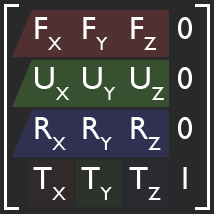
(To clear up any confusion that might exist, this is the format a transformation matrix takes in the application I'm working with:)

aamove11.gif

First, I compute the local-space transformation:

aamove12.gif

If I'm in the ordinary, local movement mode, then this is all I need. If not, I'll still want the rotation value from the above, but then I have to launch into computing the proper translation value such that X and Z are parallel to the ground and Y is straight up.

To do that, I construct a new matrix which effectively gives me this transformation. The normalized cross product of the original forward vector and global Y gives me my right vector:

aamove13.gif

Then, if I take the cross product of global Y and my new right vector, I have the forward vector I've been looking for:

aamove14.gif

In order for this new matrix to have the same scaling values as the original, I have to rescale each vector according to its original length. I don't like doing this, since it means multiple square roots per frame while the camera is moving in this mode. If there's a fundamentally better approach, mathematically speaking, that'd be great, but worst case, I could probably just disallow non-uniform scaling and keep track of a single scale factor for the camera if it becomes a problem (and it's probably not a huge deal).

aamove15.gif

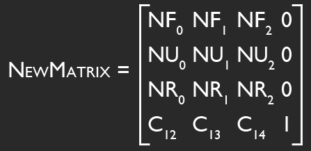
With that done, I can construct my new matrix:

aamove16.gif

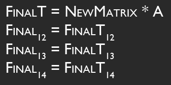
Then I can calculate the final translation matrix, and use it to alter the transformation matrix computed in the first step:

aamove17.gif

I've tested this, and it appears to give me exactly what I was looking for originally. If there's an obvious flaw or inefficiency in the way I'm going about it, I'd love to hear about it, but otherwise I'm happy that I found what I was looking for.

Thanks a lot for the help, haegarr. Like I said, I'm not formally educated in this sort of math, so having any sort of explanation from someone who understands it more intuitively is a great help. Working out this problem (and others like it) has given me an appreciation for the power of matrix transformations, and I think I'm slowly coming to understand that power as well. Slowly.
Nice that your solution works. However I have some comments...


The matrix layout shown in your previous post is the one used for row vectors (where all my explanations above were done with column vectors in mind). Row vectors and column vectors a related by the so-called transpose operator (often denoted by a superscripted t or T). There is a feature with transposition that re-orders the parts as in
( M[sub]1[/sub] * M[sub]2[/sub] )[sup]t[/sup] = M[sub]2[/sub][sup]t[/sup] * M[sub]1[/sub][sup]t[/sup]
which is important, because it shows that the "local" and "global" sides of a transformation depend on whether one uses row or else column vectors. Above I've used column vectors and the "local" side was hence at the right. But when using row vectors the "local" side is on the left according to the formula seen above.

In your example
Final = C * A
the A is applied on the right of C and hence w.r.t. the global space (because of using row vectors). If it nonetheless works well as local movement as you've stated, then I assume that the shown matrix layout isn't correct w.r.t. its mathematical meaning (perhaps because it is a copy of the memory layout). Otherwise we have a different understanding of the meaning of C and A.


Scaling is a problem. I'd avoid allowing scaling wherever possible. Especially scaling with the camera matrix seems me unnecessary (zooming can be done with the projection matrix). It is often sufficient to scale objects by mesh (e.g. in the content pipeline or during import) instead of during runtime. What means "translate by 128 units" if there is a scaling? Just my 2 Cents.


The T(...) in my suggestion means a translation matrix that is build from the specified argument. The argument is a scaled direction vector. So T(...) simply inserts the components of the argument vector into the fields T[sub]x[/sub], T[sub]y[/sub], and T[sub]z[/sub], resp., of your (initially identity) matrix.


Regarding to the complexity of your solution... It is definitely more complex than needed. If [ C[sub]0[/sub] C[sub]1[/sub] C[sub]2[/sub] ] denotes the (possibly scaled) forward vector of C, then
[ C[sub]0[/sub] 0 C[sub]2[/sub] ] / | [ C[sub]0[/sub] 0 C[sub]2[/sub] ] | * | [ C[sub]0[/sub] C[sub]1[/sub] C[sub]2[/sub] ] |
should give you the same as NewForward (i.e. also scaled). Computing NewUp and NewRight is not needed. Using the above vector (scaled by the translational amount) in T(...) and multiplying T on the right of the current C gives the new C.

This topic is closed to new replies.

Advertisement