Per-vertex lighting - Are these ugly lines normal?

Started by
9 comments, last by Narf the Mouse 11 years, 10 months ago
I am lighting a patch of terrain per-vertex in webgl, and finding highlights that stand out way too much between some vertices. Is that normal? Does switching to per-pixel lighting magically solve that. If I smooth out the terrain does it go away?

Here is a live example:
http://dl.dropbox.co...in/terrain.html

example.png

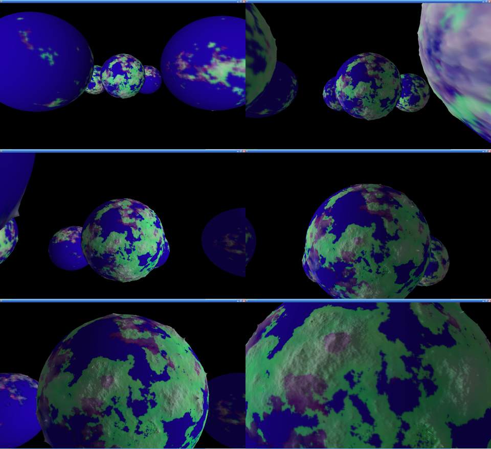
Separate topic: I am showing the vertex normals to prove they are reasonably sane and they appear to be. I tried to draw lines by drawing triangles where two points are identical, but nothing was displayed at all, so I offset one of the points by a small amount, which is why the lines look like needles. Is that normal? What is the correct way to render lines?

My main issue is that the linear interpretation of the light weighting between vertices just seems ugly. Will interpolating the normals and calculating the light weighting per pixel improve things at all for a directional light?

Here's my glsl:


<script id="shader-fs" type="x-shader/x-fragment">
precision mediump float;

varying vec4 vColor;
varying vec3 vLightWeighting;

void main(void) {
gl_FragColor = vec4(vColor.rgb * vLightWeighting, vColor.a);
}
</script>

<script id="shader-vs" type="x-shader/x-vertex">
attribute vec3 aVertexPosition;
attribute vec3 aVertexNormal;
attribute vec4 aVertexColor;

uniform mat4 uMVMatrix;
uniform mat4 uPMatrix;
uniform mat3 uNMatrix;

uniform vec3 uAmbientColor;

uniform vec3 uLightingDirection;
uniform vec3 uDirectionalColor;

varying vec4 vColor;
varying vec3 vLightWeighting;

void main(void) {
gl_Position = uPMatrix * uMVMatrix * vec4(aVertexPosition, 1.0);
vColor = aVertexColor;

vec3 transformedNormal = uNMatrix * aVertexNormal;
float directionalLightWeighting = max(dot(transformedNormal, uLightingDirection), 0.0);
vLightWeighting = uAmbientColor + uDirectionalColor * directionalLightWeighting;
}
</script>


I did something similar to this with per-vertex lighting (although using the standard pipeline, not glsl) a few years ago and didn't see these kinds of artifacts:
http://claritydevjou...ss-week-11.html
Week11ZoomInSmall.png
Advertisement
The lighting pattern/artifact is an unfortunate problem when you have a fixed-repeating grid of lowly tessellated heightmap data. Doing per-pixel lighting does not necessarily help (but can alleviate the issue), since the geometry position and normal data is interpolated across the geometry. As possible solutions, I have heard people choosing randomly the diagonal split direction they chop up the height map quads into two triangles. This makes the pattern a bit more random, and not repeating in an obvious fashion. Another option might be to add a bit of noise to the computed lighting values to de-emphasize the repeating pattern.

When you render a degenerate triangle with at least two of the three coordinates being equal, there's a good chance no pixels will be rasterized. One can either use GL_LINE_LIST or GL_LINE_STRIP to draw lines, or use a pair of triangles to produce quads oriented towards the camera in billboard fashion to make them look like fat lines.
Once you apply a typical ground texture, it is very difficult to notice.
-----Quat
clb - thanks for the tips. I switched to GL_LINES for the normal lines. No more silly needles!

I tried per-pixel lighting and confirmed what I suspected - there is no point in per-pixel lighting with a directional light. You need point lighting.
example2.png
Live example: http://dl.dropbox.com/u/17165428/terrain/perpixel.html

In the example image, I dropped out the ambient light and am just using the directional component. You both suggested adding noise to the problem, but I'd like to start from something a little less ugly to begin with. I might try smoothing the normals now that I have a better idea what that actually means.

there is no point in per-pixel lighting with a directional light. You need point lighting.


There should be a difference if you've implemented it correctly. Remember to renormalize the incoming interpolated normals in the fragment shader.
I was absolutely sure that I had re-normalized. Until I looked. You're right, it is better and different when the fragment's interpolated normal is re-normalized.

It's still not great. I'll post pictures later. It's better, but it doesn't make nearly as striking an improvement as smoothing the normals. Again, I will post pictures later. Smoothing the normals was the answer I was looking for, I think.
I completely solved this problem using a combination of catmull-rom interpolation (for the heights) and bspline interpolation (for the normals)
This is an expensive solution but gives C2 (perfectly smooth) normals that look fantastic.
You can see how it looks on my blog http://skytiger.wordpress.com/2010/11/28/xna-large-terrain/
Splines. Yes. Good answer. :) That blog post is full of interesting information. Thanks for posting, skytiger.

I kept staring at those nasty linear interpolations and thinking there ought to be a better way. It would be pretty cool if you could define a non-linear interpolation between the vertex and fragment shaders or if the fragment shader could be aware of non-interpolated vertex data.

I was surprised the difference it makes even doing a very clumsy smoothing pass on the vertex normals.
skytiger, a question about how you are interpolating points in your grid:


I would like to use Catmull Rom to subdivide my grid. If I have points defined at each 1.0 unit interval and I want to get the point for x,y = 2.5, 2.5, I could generate values for y=2.5 for x 1 through 4. Then with 4 samples for y=2.5, I could interpolate for x=2.5 on that intermediate spline.

I hope that makes sense, but it's obviously the wrong approach. The subdivision would be more oriented to one axis than the other. I'm having trouble explaining what I mean by that without writing a paragraph about it. Maybe it's good enough, or maybe the math magically works in a way that is not intuitive to me.

I know there are splines you can use on surfaces, but I really like how Catmull Rom passes through the control points.
"more oriented to one axis than the other" // I don't think it matters, if you switch the primary axis you may get a different result, but it will still be correct ...
also if you use Catmull Rom to calculate normals you will get similar artifacts to Linear Interpolation
that is why I "mix" catmull rom and bspline (technically incorrect but results are fantastic)

This topic is closed to new replies.

Advertisement