The key to eliminating filtering, whether it's in Blender or in a game, is to ensure that there is exactly 1:1 correspondence between the pixels being drawn and the region of the buffer they are being drawn to. Any change in scale or stretching will result in filtering of some sort, and you will have to plan accordingly. You can use nearest filtering, but there will still be filtering. This is actually the biggest hurdle when trying to do a pixel-perfect translation from 2D to 3D. Although, of course, you also have to worry about filtering if you do traditional 2D with scaling, so there's that.
In Blender, you can reduce filtering by going to the Texture->Image Sampling panel, turning off Mip Maps and interpolation, and cranking down the filter size as low as it will go. But you also have to ensure that your object is scaled relative to the viewpoint correctly, so that there is a 1:1 pixel mapping. Also, I notice that in your posted image, on the right, there is a bit of sloppiness in your tile. To be pixel-perfect, or as near to it as can be achieved, you need to ensure that your tiles are correct. A 2:1 tile ratio has cell lines that are exactly 2 pixels horizontally for every 1 pixel vertically; in your tile, there are a couple spots on the cell boundary that don't follow the pattern precisely, and this can have implications when drawing. That is a minor nitpick, though.
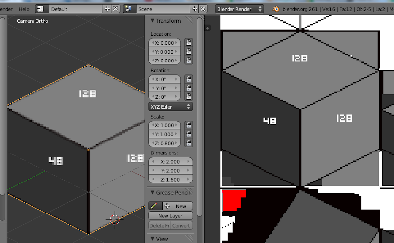
Getting the math right for pixel-perfect is the trickiest part of the process. You also have to ensure the quality of the asset creation process. I have found that, for best results, a 2:1 isometric tile hold approximately to this template:

That is zoomed, of course. You can see that all the edge lines hold to the 2:1 line ratio. In the image, the dark zones indicate areas where padding may be placed, in order to mitigate what filtering may take place. Extra padding around the outside may be necessary if the sprite is to be scaled. The padding between the top and the walls should match the top, and not the walls, since those rows of padding will be visible on tiles of the same level placed adjacent to one another, without tiles on top of them.
The main areas where you need to do some calculating are:
1) The orthographic projection matrix, and how it relates to the drawing size of the tile cubes. My personal method is to visualize each tile, as in the template above, as being some number of units in size. Each 2-pixel wide block in the cell lines denotes a unit, so a tile that is 64 pixels wide would denote a 16x16 unit cell. So if I draw my cubes as 16x16xH (height varies, depending), and use integer math for coordinates and locations, then I can ensure that tiles will be drawn on whole-pixel locations, and filtering is reduced. This requires special consideration in calculating the projection matrix.
My method, then, of calculating the orthographic matrix is to divide the screen horizontal resolution by the width, in pixels, of a tile. (64, in the case of the above magnified template). Then I multiply this value by the world size of a tile (16, in my system) and multiply that result by 1.41421356237 (The square root of 2). The reason for this is that, given a camera rotated 45 degrees around the vertical axis, you are viewing a tile not edge-wise, but diagonally. The distance between the corners of a square whose sides are 1x1 is, of course, the square root of 2.
With that calculated value, I multiply by the aspect ratio to get the orthographic height of the viewport, then use those values to set the ortho matrix. To illustrate, here is a bit of code to do just that in OpenGL:
void CIso::applyCamera()

{

    // Get the viewport resolution

    GLint viewport[4];

    glGetIntegerv( GL_VIEWPORT, viewport );


    // Set the projection matrix

    glMatrixMode(GL_PROJECTION);

    glLoadIdentity();

    float aspect=(float)viewport[3]/(float)viewport[2];

    float screen_tiles=(float)viewport[2] / (float)tile_pixel_width_;

    float ortho_width=screen_tiles*(float)tile_world_size_*1.414213562373f;

    float ortho_height=ortho_width * aspect;

    glOrtho(-ortho_width/2, ortho_width/2, -ortho_height/2, ortho_height/2, 0.0f, 1000.0f);


    // Set the camera, pointed at (x_,z_), 30 degrees around X and 45 degrees around Z. 100 units (arbitrarily chosen, will probably need to be larger for a bigger map, to

    // Prevent far-plane clipping

    glMatrixMode(GL_MODELVIEW);

    glLoadIdentity();

    glTranslatef(0,0,-100);

    glRotatef(30,1,0,0);

    glRotatef(-45.0f,0,1,0);

    glTranslatef(-x_,0, -z_);

}
That is working code from the demo that sets the projection matrix. The member
tile_pixel_width_ of that class is set during initialization, to the width (in pixels) of a tile. 64, with the above template. The member
tile_world_size_ is set by dividing the tile pixel width by 4, for a 16x16xH unit tile in the case of the above template.
2) Tile height. If you set up a 30 degree camera (the angle needed for a 2:1 projection) and view a cube, you will notice that the cube vertical faces are fore-shortened, due to the angle of the viewpoint. There needs to be careful consideration for the correspondence between the tile sprite and the cube primitive that is drawn. The height of the cube primitive needs to be scaled correctly to correspond with that foreshortening. This can take a little bit of trigonometry, but once you wrap your head around it it's not too complicated. In the case of my template tile above, the tile is a total of 64x48 pixels. (The rest is padding to bring it to 64x64.) That means 32 of the pixels are taken by the top of the tile, leaving 16 for the vertical faces. A bit of trig gives me the totally arbitrarily funky value of ~0.40824829f as the height to scale the unit-sized cube to in order to match the tile template.
With that in place, the rest is pretty simple. I put together a small demo in C++, using the latest RC of SFML 2.0. (I don't use XNA or C#.) But the code should be relatively explanatory. It's a quick, one-off demo meant to show the concepts, rather than a comprehensive prototype, but it works.
The framework:
main.cpp
[spoiler]
#include <iostream>

#include <SFML/Window.hpp>

#include <SFML/System.hpp>

#include <SFML/Graphics.hpp>

#include <cmath>

#include <sstream>

#include "app.h"

#include "iso.h"


int main()

{

	 CApp app;

	 app.setVideoMode(1024, 768, false, true);

	 CIso iso(64);

	 iso.create(8,8,8);

	 iso.setPosition(0,0);

	 iso.createTile("grasstile.png", TILE);

	 iso.createTile("dirttile.png", TILE);

	 iso.createTile("leftramptile.png", LEFTRAMP);

	 iso.createTile("rightramptile.png", RIGHTRAMP);

	 iso.setNode(0,0,0,0);

	 iso.setNode(1,0,0,0);

	 iso.setNode(0,0,1,0);

	 iso.setNode(1,0,1,0);

	 iso.setNode(0,1,0,0);

	 iso.setNode(0,1,2,1);

	 iso.setNode(0,0,2,1);

	 iso.setNode(2,0,0,1);

	 iso.setNode(0,0,3,2);

	 iso.setNode(3,0,0,3);

	 iso.setNode(1,1,0,3);

	 float x=0, z=0;

	 unsigned int curscreen=0;

	 while (app.isOpen())

	 {

		 sf::Event event;

		 float thistime=app.getTime();

		 if (app.pollEvent(event))

		 {

			 if (event.type == sf::Event::Closed)

			 {

				 app.close();

				 break;

			 }

			 if (event.type==sf::Event::KeyPressed)

			 {

				 if(event.key.code==sf::Keyboard::S)

				 {

					 std::stringstream filename;

					 filename << "screen" << curscreen++ << ".png";

					 app.screenshot(filename.str().c_str());

				 }

			 }

		 }

		 app.clear();

		 iso.render();

		 // Update the window

		 app.swap();

		 //float elapsed=app.getTime()-thistime;

		 float elapsed=app.getTime();

		 x=64+sin(elapsed)*64;

		 z=64+cos(elapsed)*64;

		 iso.setPosition(x,z);

	 }

	 return EXIT_SUCCESS;

}
[/spoiler]
app.h
[spoiler]
#ifndef APP_H

#define APP_H

#include <SFML/Window.hpp>

#include <SFML/System.hpp>

#include <SFML/Graphics.hpp>

#include <string>

#include <map>

class CApp

{

    public:

    CApp();

    ~CApp();

    bool setVideoMode(int w, int h, bool fullscreen, bool vsync);

    bool isOpen();

    void clear();

    void swap();

    void close();

    bool pollEvent(sf::Event &event);

    void screenshot(const char *name);

    float getTime();

    private:

    sf::Window window_;

    sf::Clock clock_;

};

#endif
[/spoiler]
app.cpp
[spoiler]
#include "app.h"

#include <vector>

#include <GL/gl.h>

CApp::CApp() : window_(), clock_()

{

}

CApp::~CApp()

{

    window_.close();

}

bool CApp::isOpen()

{

    return window_.isOpen();

}

bool CApp::setVideoMode(int w, int h, bool fullscreen, bool vsync)

{

    if(fullscreen)

    {

	    sf::VideoMode mode(w,h);

	    if(!mode.isValid())

	    {

		    // Not a supported full-screen mode

		    return false;

	    }

    }

    window_.create(sf::VideoMode(w,h,32), "Isometric Test", (fullscreen==true) ? sf::Style::Fullscreen : sf::Style::Close);

    if(vsync) window_.setVerticalSyncEnabled(true);

    glEnable(GL_TEXTURE_2D);

    glEnable(GL_DEPTH_TEST);

    glEnable(GL_ALPHA_TEST);

    glEnable(GL_BLEND);

    glDepthFunc(GL_LEQUAL);

    glBlendFunc(GL_ONE, GL_ONE_MINUS_SRC_ALPHA);

    glAlphaFunc(GL_GREATER, 0.0);

    glEnableClientState(GL_VERTEX_ARRAY);

    glEnableClientState(GL_TEXTURE_COORD_ARRAY);


    return true;

}

void CApp::close()

{

    window_.close();

}

void CApp::clear()

{

    glClearColor(0.0f,0.0f,0.0f,0.0f);

    glClear(GL_COLOR_BUFFER_BIT | GL_DEPTH_BUFFER_BIT);

}

void CApp::swap()

{

    window_.display();

}

bool CApp::pollEvent(sf::Event &event)

{

    return window_.pollEvent(event);

}

void CApp::screenshot(const char *name)

{

    sf::Vector2u size=window_.getSize();

    if(window_.setActive(true))

    {

	    std::vector<sf::Uint8> pixels(size.x*size.y*4);

	    sf::Uint8 *pixelptr=&pixels[0];

	    glReadPixels(0,0,size.x, size.y, GL_RGBA, GL_UNSIGNED_BYTE, pixelptr);

	    unsigned int pitch=size.x*4;

	    for(unsigned y=0; y<size.y/2; ++y)

	    {

		    std::swap_ranges(pixelptr+y*pitch, pixelptr+(y+1)*pitch, pixelptr+(size.y-y-1)*pitch);

	    }

	    sf::Image img;

	    img.create(size.x, size.y, pixelptr);

	    img.saveToFile(name);

    }

}

float CApp::getTime()

{

    return clock_.getElapsedTime().asSeconds();

}
[/spoiler]
And the isometric map code:
iso.h
[spoiler]
#ifndef ISO_H

#define ISO_H

#include <SFML/Graphics.hpp>

#include <GL/gl.h>

#include <vector>

enum ETileShapes

{

    TILE,

    LEFTRAMP,

    RIGHTRAMP

};

struct STile

{

    STile(std::string &texname, ETileShapes shape);

    sf::Texture tex_;

    sf::Vector3f *verts_;

    sf::Vector2f *uvs_;

    unsigned int *indices_;

    unsigned int numverts_;

    unsigned int numindices_;

};

class CIso

{

    public:

    CIso(unsigned int tile_pixel_width);

    ~CIso();

    void create(unsigned int width, unsigned int height, unsigned int depth);

    void setNode(unsigned int x, unsigned int y, unsigned int z, unsigned int tile);

    void fill(unsigned int index);

    void setPosition(unsigned x, unsigned z);

    void render();

    void createTile(const char *imgname, ETileShapes shape);

    private:

    std::vector<unsigned int> nodes_;

    unsigned int width_, height_, depth_;

    std::vector<STile> tiles_;

    float x_, z_;

    unsigned int tile_world_size_, tile_pixel_width_;

    void applyCamera();

    void renderNode(unsigned int x, unsigned int y, unsigned int z);


};

#endif
[/spoiler]
iso.cpp
[spoiler]
#include "iso.h"

#include <iostream>

static float ht=0.40824829f;

// Basic Shapes (ETileShapes)

// TILE

// Verts

sf::Vector3f tile_verts[7]=

{

    sf::Vector3f(0,ht,0),

    sf::Vector3f(0,ht,1),

    sf::Vector3f(1,ht,1),

    sf::Vector3f(1,ht,0),

    sf::Vector3f(0,0,1),

    sf::Vector3f(1,0,1),

    sf::Vector3f(1,0,0)

};

// UVs

sf::Vector2f tile_uvs[7]=

{

    sf::Vector2f(0.5,0),

    sf::Vector2f(0, 0.25),

    sf::Vector2f(0.5, 0.5),

    sf::Vector2f(1,0.25),

    sf::Vector2f(0,0.5),

    sf::Vector2f(0.5,0.75),

    sf::Vector2f(1,0.5)

};

// Indices

unsigned int tile_indices[18]=

{

    0,1,2, 0,2,3, 1,4,2, 2,4,5, 3,2,6, 2,5,6

};

// LEFTRAMP

// Verts

sf::Vector3f left_verts[5]=

{

    sf::Vector3f(0,ht,0),

    sf::Vector3f(0,0,1),

    sf::Vector3f(1,0,1),

    sf::Vector3f(1,ht,0),

    sf::Vector3f(1,0,0)

};

// UVs

sf::Vector2f left_uvs[5]=

{

    sf::Vector2f(0.5,0),

    sf::Vector2f(0,0.5),

    sf::Vector2f(0.5,0.75),

    sf::Vector2f(1,0.25),

    sf::Vector2f(1,0.5)

};

// Indices

unsigned int left_indices[9]=

{

    0,1,2, 0,2,3, 3,2,4

};

// RIGHTRAMP

// Verts

sf::Vector3f right_verts[5]=

{

    sf::Vector3f(0,ht,0),

    sf::Vector3f(0,ht,1),

    sf::Vector3f(1,0,1),

    sf::Vector3f(1,0,0),

    sf::Vector3f(0,0,1)

};

// UVs

sf::Vector2f right_uvs[5]=

{

    sf::Vector2f(0.5,0),

    sf::Vector2f(0,0.25),

    sf::Vector2f(0.5,0.75),

    sf::Vector2f(1,0.5),

    sf::Vector2f(0,0.5)

};

// Indices

unsigned int right_indices[9]=

{

    0,1,2, 0,2,3, 1,4,2

};


STile::STile(std::string &texname, ETileShapes shape) : tex_(), verts_(0), uvs_(0), indices_(0), numverts_(0), numindices_(0)

{

    tex_.loadFromFile(texname.c_str());

    tex_.setSmooth(false);

    switch(shape)

    {

	    case TILE: numverts_=7; numindices_=18; verts_=tile_verts; uvs_=tile_uvs; indices_=tile_indices; break;

	    case LEFTRAMP: numverts_=5; numindices_=9; verts_=left_verts; uvs_=left_uvs; indices_=left_indices; break;

	    case RIGHTRAMP: numverts_=5; numindices_=9; verts_=right_verts; uvs_=right_uvs; indices_=right_indices; break;

	    default: break;

    }

}


CIso::CIso(unsigned int tile_pixel_width) : tile_world_size_(tile_pixel_width/4), tile_pixel_width_(tile_pixel_width)

{

}

CIso::~CIso()

{

}

void CIso::applyCamera()

{

    // Calculate the orthographic width/height for the screen projection based on the tile pixel size

    // This is calculated as so:

    // The World-space size of a tile is tile_pixel_width/4. This means that, for example, a tile whose pixel width

    // is 64 represents a tile that is 16x16 units in world size. So to cross the tile, an actor has to move 16 steps.

    // The number of tiles that are visible across the screen is calculated by dividing the screen resolution width by

    // tile_pixel_width. Now, this represents the number of tiles visible across the screen, but those tiles are viewed at

    // a 45 degree angle around the Y axis, so the actual number of tiles visible would be this result divided by the

    // square root of 2. This gives you the total number of tiles across that the screen is. This result is then multiplied

    // by the tile world size (16, in the case of a 64x64 tile sprite) to get the orthographic width of the screen.

    GLint viewport[4];

    glGetIntegerv( GL_VIEWPORT, viewport );

    glMatrixMode(GL_PROJECTION);

    glLoadIdentity();

    float aspect=(float)viewport[3]/(float)viewport[2];

    float screen_tiles=(float)viewport[2] / (float)tile_pixel_width_;

    float ortho_width=screen_tiles*(float)tile_world_size_*1.414213562373f;

    float ortho_height=ortho_width * aspect;

    glOrtho(-ortho_width/2,ortho_width/2,-ortho_height/2,ortho_height/2,0.0f, 1000.0f);

    glMatrixMode(GL_MODELVIEW);

    glLoadIdentity();

    glTranslatef(0,0,-100);

    glRotatef(30,1,0,0);

    glRotatef(-45.0f,0,1,0);

    glTranslatef(-x_,0, -z_);

}

void CIso::create(unsigned int width, unsigned int height, unsigned int depth)

{

    width_=width;

    height_=height;

    depth_=depth;

    nodes_.resize(width*height*depth);

    fill(1000);

}

void CIso::setNode(unsigned int x, unsigned int y, unsigned int z, unsigned int tile)

{

    unsigned int index=z*width_*height_ + y*width_ + x;

    if(index>nodes_.size()-1) return;

    nodes_[index]=tile;

}

void CIso::fill(unsigned int index)

{

    for(unsigned int c=0; c<nodes_.size(); ++c) nodes_[c]=index;

}

void CIso::setPosition(unsigned int x, unsigned int z)

{

    //unsigned int tx=(unsigned int)(x/64);

    //unsigned int tz=(unsigned int)(z/64);

    //x_=(float)tx*64.0f;

    //z_=(float)tz*64.0f;

    //unsigned int tx=(unsigned int)(x*16);

    //unsigned int tz=(unsigned int)(z*16);

    //x_=(float)tx/16.0f;

    //z_=(float)tz/16.0f;

    x_=(float)x;

    z_=(float)z;

}

void CIso::createTile(const char *imgname, ETileShapes shape)

{

    std::string s(imgname);

    tiles_.push_back(STile(s, shape));

}

void CIso::renderNode(unsigned int x, unsigned int y, unsigned int z)

{

    unsigned int index=z*width_*height_ + y*width_ + x;

    //std::cout << index << std::endl;

    if(index>=nodes_.size()) return;

    unsigned int tile=nodes_[index];

    if(tile>=tiles_.size()) return;

    //std::cout << "render" <<std::endl;

    glMatrixMode(GL_MODELVIEW);

    glPushMatrix();

    glTranslatef(x*tile_world_size_,y*tile_world_size_*0.40824829f,z*tile_world_size_);

    glScalef(tile_world_size_, tile_world_size_, tile_world_size_);

    STile *tile_ptr=&tiles_[tile];

    if(!tile_ptr) return;

    tile_ptr->tex_.bind();

    glVertexPointer(3,GL_FLOAT,0,tile_ptr->verts_);

    glTexCoordPointer(2,GL_FLOAT,0,tile_ptr->uvs_);

    glDrawElements(GL_TRIANGLES, tile_ptr->numindices_, GL_UNSIGNED_INT, tile_ptr->indices_);

    glPopMatrix();

}

void CIso::render()

{

    applyCamera();

    for(int x=width_-1; x>=0; --x)

    {

	    for(int y=height_-1; y>=0; --y)

	    {

		    for(int z=depth_-1; z>=0; --z)

		    {

			    renderNode(x,y,z);

		    }

	    }

    }

}
[/spoiler]
Here are the tiles used for the demo. (They should be in the root directory of the executable.)
dirttile.png
 grasstile.png
 leftramptile.png
 rightramptile.png

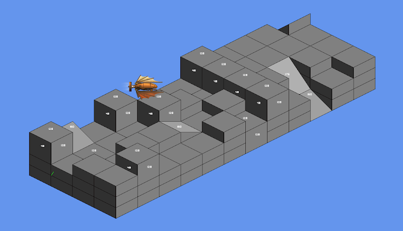
The demo sets up a tiny sample map, then enters a loop in which the camera scrolls around endlessly in a circle. Nothing fancy. The tile geometry units are hard-coded, but in a real game I'd use loadable geometry in case I needed a weird tile of some sort. Here is a shot of the demo in action:

If you zoom in, you can see that the pixels are pretty close to pixel-perfect (or, at least they were on the source image; I really can't vouch for imgur's service after they're uploaded). Filtering artifacts might occur (very occasionally) but if you pad your sprites correctly, even on the rare times they happen, they are not that noticeable.
I didn't have time at work to hack in mob sprites, but depth testing IS working correctly, and the sprites would be correctly clipped. (You can tell depth buffering is working, as the tiles are drawn from front (top, nearest corner) to back (bottom, far corner), and yet the back tiles are correctly clipped by the front tiles.