I took the challenge (and the chance to learn something about barycentric coordinates). Though I have already been beaten - thanks Lorenzo

- I'll still post my discoveries. Cause I got pictures...
("in farbe ... und bunt")For transitions my if/else cascade is not good, are more mathematical approach is due.
So, can we get e.g. a central line ? How does one express a line in barycentric coordinates ?
Ahah!Let's try this in HLSL
float3 uvw = pin.DomainLocation.xyz;

float3 r1 = float3(0.5, 0.5, 0  );  // first point
float3 s1 = float3(0  , 0  , 1  );  // second point
float  t1 = determinant(float3x3(uvw,r1,s1)); // line equation (line is at t1 = 0)

// use this value for transition
float transition = 10;
float x = smoothstep(0, 1, transition * t1 + 0.5);

return float4(x,x,x,1);
That looks useful:
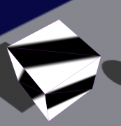
The other lines...
float3 uvw = pin.DomainLocation.xyz;

float3 r1 = float3(0.5, 0.5, 0  );
float3 s1 = float3(0  , 0  , 1  );
float  t1 = determinant(float3x3(uvw,r1,s1));

float3 r2 = float3(0.5, 0, 0.5  );
float3 s2 = float3(0  , 1, 0    );
float  t2 = determinant(float3x3(uvw,r2,s2));

float3 r3 = float3(0  , 0.5, 0.5);
float3 s3 = float3(1  , 0  , 0  );
float  t3 = determinant(float3x3(uvw,r3,s3));

float transition = 10;
float r = smoothstep(0, 1, transition * t1 + 0.5);
float g = smoothstep(0, 1, transition * t2 + 0.5);
float b = smoothstep(0, 1, transition * t3 + 0.5);

return float4(r,g,b,1);
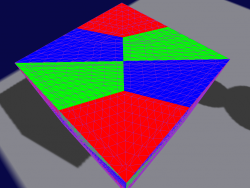
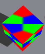
Yep, we can work with that:
Now, we combine the parts to get those hex sections. This is done using intersection. For blending weights one can use e.g. min(a,b):
//... r,g,b like before
float rr = min(r,g);
float gg = min(g,b);
float bb = min(b,r);
return float4(rr,gg,bb,1);
Ooops:
Naah, intersect with the complement of the next line...
//... r,g,b like before
float rr = min(r,1-g);
float gg = min(g,1-b);
float bb = min(b,1-r);
return float4(rr,gg,bb,1);
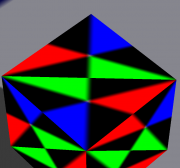
... looks better:
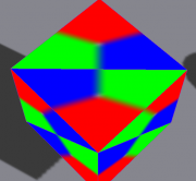
Not quite happy with the centre. An alternative is to use multiplication:
float rr = r*(1-g);
float gg = g*(1-b);
float bb = b*(1-r);
Too dark at the transitions. Well, blending weights should sum to 1, so lets normalize them
float3 rgb = float3(rr,gg,bb);
float s = dot(float3(1,1,1), rgb);
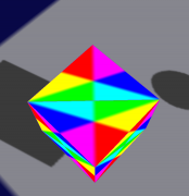
return float4(rgb / s, 1);
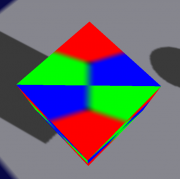
Yep:
One can now simplify the math stuff, e.g. a determinant with (1,0,0) in it, will just evaluate to a sub-determinant.
Now this is of course fun (well, it was for me), but I wonder if a different approach is actually better. I think starting with an alternative geometry, e.g. 6 triangles for one hex patch could simplify this greatly. I expect you could generate the appropriate texcoords earlier instead of going this - now rather convoluted - approach through the barycentrics.