Raising the Deferred Depth Buffer Reconstruction Bar

Started by
17 comments, last by EnlightenedOne 9 years, 8 months ago

The remaining hurdle involves the negative normals of my cube being lit when the light is hitting the back of the surface (as if the normal is the inverse of the way I would like it to be)


Remember, that this is to some degree expected behavior. Imagine a surface like this:

  x <-- Light source

  ---------                         -------------
           \                       /
            \                     /
             \                   /
              \    back side    /
                --------------- 
                   front side
Without shadows, the light source can light the left slope, even though it is behind the surface, because it is in a way in front of the left slope. You get the same effect from normal maps with strong normals.


I have tried many permutations of NBT on the cube face I have left empty but even with no NBT data the flat lighting still behaves as though the face was facing the other way, I am lead to believe it has to a bug in my lighting.


It looks correct in the images. Lighting is the flat grey of the ambient light, with no influence from the light sources. What behavior are you expecting?

I am not sure if my home brew Cube is at fault or my shader code:


The shader code looks ok, the tangents of the cube look wrong. Actually, it kind of depends on your normal map, which you didn't post here.
A tangent space normal map encodes the normals relativ to ... well the tangent space. This is a fancy way of saying, that the red component encodes, how much the normal is bend towards the right in the texture, which is the direction of increasing X coordinates in the texture, or the direction of increasing u coordinates on the UV mapped model. Similarly, the green component encodes, how much the normal is bend towards the direction of increasing Y in the texture, or the direction of increasing V in the UV mapped moddel. So, the tangent associated with the red component (in your shader the "tangent") should point in the object space direction, in which the u part of the UV coordinates increases. The tangent associated with the green component (in your shader the "binormal") should point in the objects space direction, in which the v part of the UV coordinates increases. I hand checked a couple of your cube triangles, and sometimes, the tangents were negated.

Now, if you like brain teasers, you can obiously change the encoding of your normalmaps, for example by inverting the red or green channels, in which case your tangents would have to be inverted too. But IMO this only makes it more complicated to reason about it, and you should keep it as simple as possible.

If you are having trouble, computing consistent normals and tangents by hand, maybe you should write some code for that. You will need it eventually, when you load models from files.
Advertisement

Without shadows, the light source can light the left slope, even though it is behind the surface, because it is in a way in front of the left slope. You get the same effect from normal maps with strong normals.

- Absolutely I am not expecting zero bleed through on critical angles, I think I may have just taken some unclear screen shots in my last post.

I have been trying to map in world rather than face UV orientation which could potentially explain why the normal might not be as I expect, the only trouble is the sheer volume of permutations I have tested which make me suspect a deeper fault.

Let me have another go at those images with simpler angles.

xPositiveLightNear (light behind camera):

xPositiveLightNear.jpg

xPositiveLightFar (light behind box):

xPositiveLightFar.jpg

The above look good slight bleed through on critical angles in reflection as qualified by your description.

xNegativeLightNear (light behind camera on negative side) (please ignore the lines in the distance that is an irrelevant attempt at loading a model from a file):

xNegativeLightNear.jpg

xPositiveLightFar (light behind surface perfectly lit):

xNegativeLightFar.jpg

If you take a look you can see the normal looks as if it is on the other side of the face. If the NBT is so wrong that I am causing this by design as you suggest I will continue to investigate by manual modification trying to use the UV orientation of the face and your description as a guide. Validating it against the working faces before proceeding.

I know it might sound silly but being able to write a normal mapped cube with indices is definitely something I feel I must force myself to become competent at smile.png

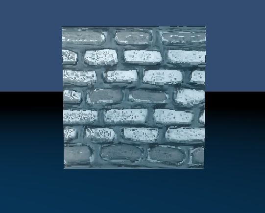
Here is the normal map:

primitiveWallNormal.png

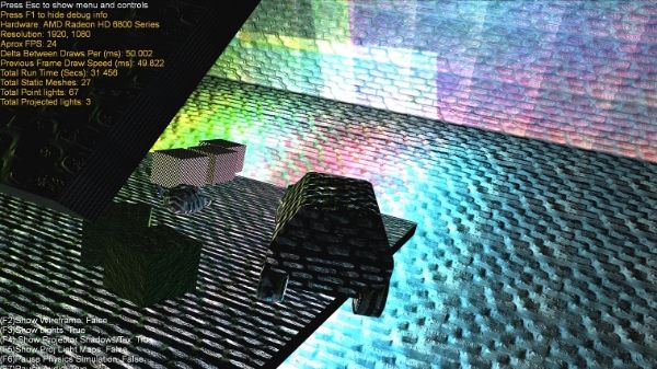
Finally and this is just for my sake to show the normal is sound, here is a DX9 forward renderer I wrote a couple of years back using the same tex, the FPS is low as I have a couple of copies of my OpenGL cube apps GBuffer sitting on the GCard and this was my stress test world with some shadow maps and demonstrative overstated parallax relief mapping etc:

d0e1bda1-8f99-49ed-9bda-b7f553df8344.jpg

I will keep picking away at the assembly of the normals as you have had a glance at the shaders, I might even try flipping it to see if the normals come through on the negative axis.

Thank you for all of your input so far.

Probably unrelated to your current problem but:

Here is the normal map:
primitiveWallNormal.png

In your normal map, the blue and green channels are switched. And the quality is extremely bad, but you probably realized that.

At the risk of repeating myself: Don't experiment, don't try all permutations, because you surely will miss one (like exchanging blue and green). Reason about how it should work, and figure out, at which point it deviates from your expectations.

Qualifying per pixel normals and ignoring the normal map temporarily

It appears that the texture I sent was some form of thumbnail rather than the full size image, its 128x128 in the renders above highest I have it at is 512x512.

In your normal map, the blue and green channels are switched.

- Can you qualify this?

Lets strip this back to basics of a normal map. The NBT is used to represent the Normal Bitangent Tangent axis for arbitrary rotation in model space about a vertex the normal map is the process by which this NBT is rotated per pixel along XYZ to produce a new normal.

The normal map stores axis per RGB where RGB = XYZ within the texture r0 to r256 map to normals -1x to 1x when the texture is read in the normal map values are scaled (rgb* 2 -1) to transform them between -1 and 1. In order to keep the local normal scaled relative to the tangents direction the blue channel is always kept above 128.

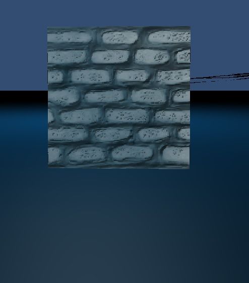
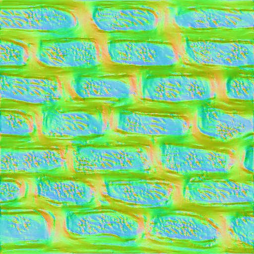
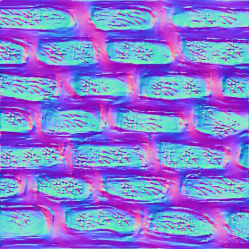
So flipping the green and blue channel sounds like a dangerous move as it will lower the brightness when the light is directly facing the surface

WallNormalGBFlip.jpg

vs

WallNormal.jpg

Arguably the pitch of the tangent might not be massively influential on the surface dulling the roughness of the surface but for this rough wall why worry? (remember the green is the inseam of mortar beween bricks so making the light increase when the light is above the face weakens realism by not faking occlusion :p

Based on my grasp of normals we can forgoe worrying about the image itself by just using a normal map which is a all 128r,128g,256b this should at least allow the NBT to be analysed without distortions, even better we can cut the middle man and multiply the tbnMatrix by vec3(0,0,1).

GeomFrag Update:


	vec3 normalMap = 2.0f * texture( normalTexture, v2UVHeightDisplacement ).xyz - 1.0f;
	normalMap = vec3(0,0,1);
	normalMap = tbnMatrix * normalMap;
	normalMap = normalize(normalMap);
	normalOut.xyz = 0.5f * (normalMap + 1.0f);

The Normal Fight Continues:

I am using these as my foundation for analysis:

http://www.gamedev.net/topic/347799-mirrored-uvs-and-tangent-space-solved/

http://www.catalinzima.com/xna/tutorials/deferred-rendering-in-xna/custom-content-processor-and-normal-mapping/

I decided that because generating an arbitrary axis is hard I would try and get blender to output a plain text xyz uv n (xyz) b(xyz) t(xyz) model but it appears this is the holy grail of things to attain. Actually it proved so difficult just to get a cube formatted in such a way that I could either read it in notepad+ or get the indicies to match up I decided to start somewhere else.

So I adapted a normal solver I had been using with certainty on a 2 axis basis but had seen elsewhere as a certified triangle normal generator and decided to see if I could not generate my NBT from the pos and uv cutting down on the number of candidate problems and giving me a very useful reusable bit of code if ever I decide to generate 3d terrain from a heightmap etc.

I am still in the process of proving that the outputs are valid before running over my math to validate the order of the UV. I will keep you posted when I have more.

Sounds good, I like the idea of skipping the normal map for now.


What I meant with "green and blue are switched" wasn't that green is inverted and blue is inverted. What I meant is that what should be in the blue channel is in the green channel and what should be in the green channel is in the blue channel.

This code


mat3 mTBNMatrix = mat3(mWUnscaled) * mat3(inTangent, inBinormal, inNormal);
//...
vec3 normalMap = texture( normalTexture, v2UVHeightDisplacement ).xyz * 2.0f - 1.0f;
normalMap = tbnMatrix * normalMap;

says, that red belongs to "inTangent", green to "inBinormal" and blue to "inNormal". In the low res version it looked like green was the color belonging to the normal.

Now, with the high res image, I'm not so sure anymore. According to the histograms, blue is indeed the component belonging to the normal, however that would mean that the faces of the bricks are all at an angle of 45° which doesn't make any sense.


I tried to compute the heightmap for that normalmap, and if I didn't mess things up it looks like this:

[sharedmedia=gallery:images:5490]

It looks a bit like you took a photo, converted that to greyscale, applied a couple of blur filters and used that as the heightmap. Any chance that's true? ;-)

My girlfriend drew the original texture for me to test out a digital track-pad and pen quickly. My Uni had paid for a license for CrazyBump and believe it or not the normal map and the height map are the result of plumbing that texture through it and clearly setting the details badly ;)

After some rather unpleasant experience trying to draw it out and having my expectations fall short of digital reality I found the holy grail I was after:

http://en.wikibooks.org/wiki/OpenGL_Programming/Modern_OpenGL_Tutorial_06

I tweaked the NBT generation slightly:


	protected void buildQuadNBTData() {
		
		//Build the data if required.
		switch (enumVertType) {
			case VERTEX_TYPE_POS_UV_NTB:
				
				//Lock the vertices in the VBO, first bind the VBO for updating
				GL15.glBindBuffer(GL15.GL_ARRAY_BUFFER, vboId);
			
				//Put the new data in a ByteBuffer (in the view of a FloatBuffer)
				FloatBuffer vertexFloatBuffer = verticesByteBuffer.asFloatBuffer();

				Vector3f normal = null;
				Vector3f binormal = null;
				Vector3f tangent = null;
				
				//Compute triangle bitangents and tangents
				for (int i = 0; i < vertices.length; i+=4) {
					Vert_PosUVNBT vertex0, vertex1, vertex2, vertex3;
					
					vertex0 = (Vert_PosUVNBT) vertices[i+0];
					vertex1 = (Vert_PosUVNBT) vertices[i+1];
					vertex2 = (Vert_PosUVNBT) vertices[i+2];
					vertex3 = (Vert_PosUVNBT) vertices[i+3];
					
					// Shortcuts for vertices
				    Vector3f v0 = vertex0.getXYZV3();
				    Vector3f v1 = vertex1.getXYZV3();
				    Vector3f v2 = vertex2.getXYZV3();
				 
				    // Shortcuts for UVs
				    Vector2f uv0 = vertex0.getUVV2();
				    Vector2f uv1 = vertex1.getUVV2();
				    Vector2f uv2 = vertex2.getUVV2();
				 
				    Vector3f deltaPos1 = null;
				    Vector3f deltaPos2 = null;
				    
					// Edges of the triangle : position delta
					deltaPos1 = Vector3f.sub(v1, v0, null);
					deltaPos2 = Vector3f.sub(v2, v0, null);

				    // UV delta
				    float s1 = uv1.x - uv0.x;
					float t1 = uv1.y - uv0.y;
					float s2 = uv2.x - uv0.x;
					float t2 = uv2.y - uv0.y;
					
				    float tmp = 0.0f;
				    if(Math.abs(s1*t2 - s2*t1) <= 0.0001f)
					{
						//Prevent Divide by zero
						tmp = 1.0f;
					}
					else
					{
						tmp = 1.0f/(s1*t2 - s2*t1);
					}

				    tangent = new Vector3f((t1*deltaPos2.x - t2*deltaPos1.x), 
								    		(t1*deltaPos2.y - t2*deltaPos1.y), 
								    		(t1*deltaPos2.z - t2*deltaPos1.z));
				    
				    binormal = new Vector3f((s1*deltaPos2.x - s2*deltaPos1.x), 
								    		(s1*deltaPos2.y - s2*deltaPos1.y), 
								    		(s1*deltaPos2.z - s2*deltaPos1.z));

				    normal = OpenGLHelper.calculateNormal(v0, v1, v2);
				    tangent.set(tangent.x*tmp, tangent.y*tmp, tangent.z*tmp);
				    binormal.set(binormal.x*tmp, binormal.y*tmp, binormal.z*tmp);

					if (Vector3f.dot(Vector3f.cross(normal, tangent, null), binormal) < 0) {
						tangent = (Vector3f) tangent.negate();
					}
					
					binormal = (Vector3f) binormal.negate();
				    vertex0.setNormalXYZ(normal.x, normal.y, normal.z);
				    vertex0.setBinormalXYZ(binormal.x, binormal.y, binormal.z);
					vertex0.setTangentXYZ(tangent.x, tangent.y, tangent.z);
					
					vertex1.setNormalXYZ(normal.x, normal.y, normal.z);
				    vertex1.setBinormalXYZ(binormal.x, binormal.y, binormal.z);
					vertex1.setTangentXYZ(tangent.x, tangent.y, tangent.z);
					
					vertex2.setNormalXYZ(normal.x, normal.y, normal.z);
				    vertex2.setBinormalXYZ(binormal.x, binormal.y, binormal.z);
					vertex2.setTangentXYZ(tangent.x, tangent.y, tangent.z);
					
					vertex3.setNormalXYZ(normal.x, normal.y, normal.z);
				    vertex3.setBinormalXYZ(binormal.x, binormal.y, binormal.z);
					vertex3.setTangentXYZ(tangent.x, tangent.y, tangent.z);
					
					vertexFloatBuffer.put(vertex0.getElements());
					vertexFloatBuffer.put(vertex1.getElements());
					vertexFloatBuffer.put(vertex2.getElements());
					vertexFloatBuffer.put(vertex3.getElements());
				}
				
				vertexFloatBuffer.flip();

				/*for (int i = 0; i < vertices.length; i++) {
					System.out.println(i + " " + vertices[i].toString());
				}*/
				
				//Rebuffer the data to the gcard ready for drawing
				GL15.glBufferSubData(GL15.GL_ARRAY_BUFFER, 0, verticesByteBuffer);

				//Unlock the buffer
				GL15.glBindBuffer(GL15.GL_ARRAY_BUFFER, 0);
				
				break;
			default:
				break;
		}	
	}

For anyone reading after generating NBT you can get the vertex out facing normal with just the triangle above and the NBT per vertex if you have defined the objects UV mapping.

I scanned everything and concluded that the box looked valid but my lighting seemed wrong, the specular was blotched and all the lighting was biased toward one vector, that is when I realised it.

In my frag shader above "vec4 normal = texture(normalTexture, UV);//2.0f * texture(normalTexture, UV) - 1.0f;"

Why do something so stupid? Because to draw my floor I have a very basic position colour vertex type using a basic shader to fill the GBuffer. I set the normal on it to be vec4(0,1,0,0) and used the simplicity of this as the basis for proving my light was ok (I was clinging to the light appearing to be right).

The valid version of my simpler normal is up test was:

normalOut = vec4(0.5f, 1.0f, 0.5f, 0.5f);

If you had not made me put a microscope over my normal textures I would never have realised it.

Thank you very much! Here is what I have now:

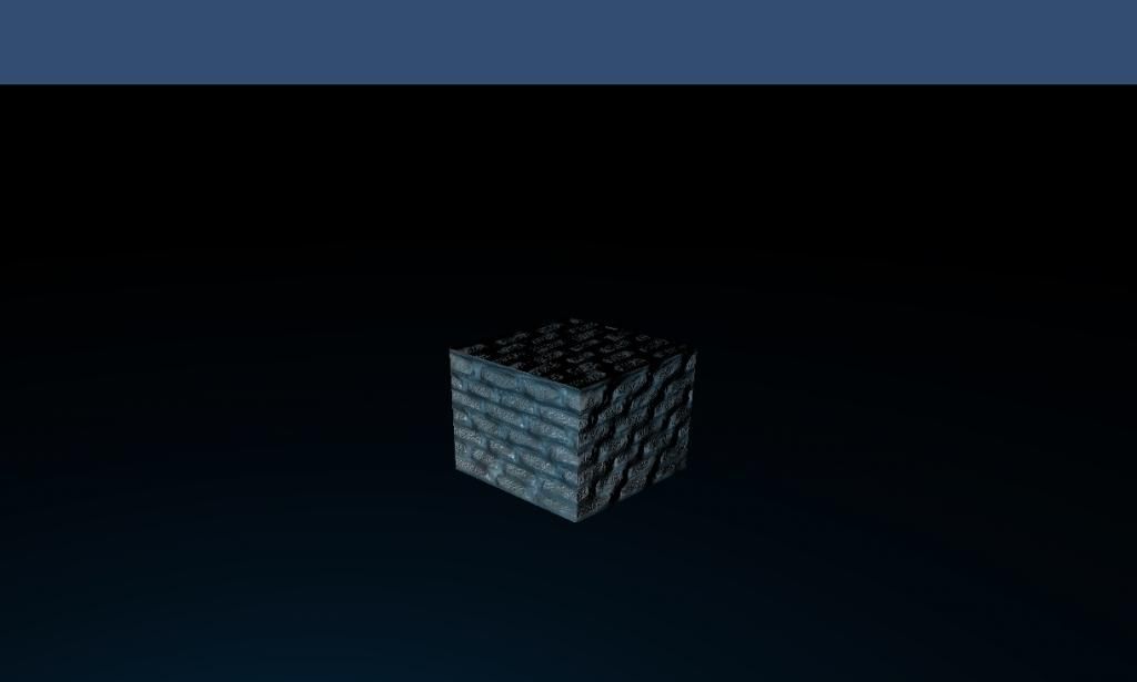
sample-1.jpg

The light is close to the ground and the floor looks a bit dark in this picture but it looks much brighter pre jpeged.

With my positions and the basic bearings back under control I can confidently progress and optimise I have many things to review for starters I will shift my normal buffer over to view space to simplify the majority of light calculations. The one thing I still do not have a handle on is the optimisation from the sample for clipping lights by the near far z depth. I will keep you posted when I have spent more time analysing how that should play out. I cant wait to plumb in some beautiful post processing smile.png

Before moving on I decided the gains from getting the near far boundaries of the light sphere clipping were well worth it. I set my light shader to just output white on anything it drew on within the zboundary so I could test the clipping.

Below is some info on my setup but I can boil it down to one core problem:

"I know that I need to get the depth in NDC space within the clipped boundaries from the projection but I am not sure how to get there in OpenGL from the view space position of my light (lVec)."

My Projection Matrix


	public static void createProjection(Matrix4f projectionMatrix, float fov, float aspect, float znear, float zfar) {

		float scale = (float) Math.tan((Math.toRadians(fov)) * 0.5f) * znear;
	    float r = aspect * scale;
	    float l = -r;
	    float t = scale;
	    float b = -t;
		
		projectionMatrix.m00 = 2 * znear / (r-l);
		projectionMatrix.m01 = 0;
		projectionMatrix.m02 = 0;
		projectionMatrix.m03 = 0;

		projectionMatrix.m10 = 0;
		projectionMatrix.m11 = 2 * znear / (t-b);
		projectionMatrix.m12 = 0;
		projectionMatrix.m13 = 0;

		projectionMatrix.m20 = (r + l) / (r-l);
		projectionMatrix.m21 = (t+b)/(t-b);
		projectionMatrix.m22 = -(zfar + znear) / (zfar-znear);
		projectionMatrix.m23 = -1;

		projectionMatrix.m30 = 0;
		projectionMatrix.m31 = 0;
		projectionMatrix.m32 = -2 * zfar * znear / (zfar - znear);
		projectionMatrix.m33 = 0;
	}

Output:

1.1179721 0.0 0.0 0.0
0.0 1.428148 0.0 0.0
0.0 0.0 -1.0000666, -1.0000334
0.0 0.0 ,-1.0 0.0
m32 = -1.0000334
m23= -1
Vector2f zw = new Vector2f(projection.m22, projection.m32);
Vector4f lvPos = OpenGLHelper.columnVectorMultiplyMatrixVector(cameraController.getActiveCameraView(), new Vector4f(lightPos.x, lightPos.y, lightPos.z, 1.0f));

public static Vector4f columnVectorMultiplyMatrixVector(Matrix4f matrix, Vector4f vector) {
     Vector4f returnVec = new Vector4f(); 

     returnVec.x = Vector4f.dot(new Vector4f(matrix.m00,matrix.m10,matrix.m20,matrix.m30), vector);
     returnVec.y = Vector4f.dot(new Vector4f(matrix.m01,matrix.m11,matrix.m21,matrix.m31), vector);
     returnVec.z = Vector4f.dot(new Vector4f(matrix.m02,matrix.m12,matrix.m22,matrix.m32), vector);
     returnVec.w = Vector4f.dot(new Vector4f(matrix.m03,matrix.m13,matrix.m23,matrix.m33), vector);
     
        return returnVec; 
    }

- I know that is a suboptimal method it will get optimised when I have this technique down. OPTIMISED REVISION BELOW

If I put the camera at xyz(-30.19929, 5.049999, 24.870947)

I notice that the light view position z is always negative, so I decided to flip the z with:
Vector4f lvPos = OpenGLHelper.columnVectorMultiplyMatrixVector(cameraController.getActiveCameraView(), new Vector4f(0, 0, 0, -1.0f));
float 53.809433(z1) = 38.809433(lvPos.z) + 15(lightRadius);
if (z1 > 0.5f) {
float 23.809433(z0) = Math.max(lvPos.z - lightRadius, 0.5f);
Now from what I understand the equation here:
float2 zBounds;
zBounds.y = saturate(zw.x + zw.y / z0);
zBounds.x = saturate(zw.x + zw.y / z1);
Is clipSpaceDepth = near clip + farClip / position in view space.
Unfortunately Humus transforms his projection into a D3D projection further obfuscating what the true values of zw represent.

			Vector2f zBounds = new Vector2f();
			zBounds.y = (zw.x + zw.y / z0);
			zBounds.x = (zw.x + zw.y / z1);
			
//Crude saturate just for qualifying that I cover this step
			if (zBounds.y > 1) {
				zBounds.y = 1;
			} else if (zBounds.y < 0) {
				zBounds.y = 0;
			}
			
			if (zBounds.x > 1) {
				zBounds.x = 1;
			} else if (zBounds.x < 0) {
				zBounds.x = 0;
			}
Worse still if I make my zw values identical to the values Humus's arrives at zw(-0.000033318996, 0.50001669) and apply the above calculation from the same position with a fairly close view angle I get some incorrect values:
0.020451155(zBounds.y) = (-0.000033318996(zw.x) + 0.5000167(zw.y) / 24.409546(z0));
0.009156551(zBounds.x) = (-0.000033318996(zw.x) + 0.5000167(zw.y) / 54.409546(z1));
Any assistance welcome smile.png

I should be able to multiply the lightView (+ radius?) with the projection then divide the z value by w to get the z depth in NDC as I would in a shader. The lightRadius by my account should screw up the vector of projection causing me to fail to reach NDC...


		//Compute z-bounds
		Vector4f lvPos = OpenGLHelper.columnVectorMultiplyMatrixVector(cameraController.getActiveCameraView(), new Vector4f(lightPos.x, lightPos.y, lightPos.z, 1.0f));
		float z1 = lvPos.z + lightRadius;

		if (z1 * -1 > 0.5) {
			float z0 = Math.max(lvPos.z - lightRadius, 0.5);

//Move from view to clip space
			Vector4f z0p = OpenGLHelper.columnVectorMultiplyMatrixVector(cameraController.getCoreCameraProjection(), new Vector4f(lvPos.x, lvPos.y, z1, 1.0f));
			Vector4f z1p = OpenGLHelper.columnVectorMultiplyMatrixVector(cameraController.getCoreCameraProjection(), new Vector4f(lvPos.x, lvPos.y, z0, 1.0f));
			
			//NDC
			z0p.z = z0p.z / z0p.w;
			z1p.z = z1p.z / z1p.w;

The above does not work but I did not expect it to, I am clearly missing something important that allows for the projection to be manipulated to extrapolate the depth in NDC.

Ok so I decided to take the advice of Ohforf sake and not try and second guess the behaviour and tricks of the DX implementation using assumptions due to the trouble it could bring.

I decided that I knew very well view * projection to clip space /w to NDC is what I wanted and I had all the wits to get there somehow:


		Vector4f lsPos = OpenGLHelper.columnVectorMultiplyMatrixVector(cameraController.getActiveCameraView(), new Vector4f(lightPos.x, lightPos.y, lightPos.z, 1.0f));
		Vector4f lsPos2 = new Vector4f(lsPos);
		lsPos.z -= lightRadius;

		if (lsPos.z*-1 > 0.5/*NEAR_DEPTH*/) {
			//Convert lPos to NDC
			lsPos = OpenGLHelper.columnVectorMultiplyMatrixVector(cameraController.getCoreCameraProjection(), new Vector4f(lsPos.x, lsPos.y, lsPos.z, lsPos.w));
			lsPos.z = lsPos.z / lsPos.w;
			
			lsPos2.z = lsPos2.z + lightRadius;
			lsPos2 = OpenGLHelper.columnVectorMultiplyMatrixVector(cameraController.getCoreCameraProjection(), new Vector4f(lsPos2.x, lsPos2.y, lsPos2.z, lsPos2.w));
			lsPos2.z = lsPos2.z / lsPos2.w;
			
			Vector2f zBounds = new Vector2f();

			zBounds.y = lsPos.z;
			zBounds.x = lsPos2.z;
			
			if (zBounds.y > 1) {
				zBounds.y = 1;
			} else if (zBounds.y < 0) {
				zBounds.y = 0;
			}
			
			if (zBounds.x > 1) {
				zBounds.x = -1;
			} else if (zBounds.x < 0) {
				zBounds.x = 0;
			}

It is three vector matrix calculations per light but Humus's genius clearly trumps mine for now. Here is the final product with 0.1 added to the pixels within the calc:

clippedLight.jpg

Sure there are clip space lights but I still find this enchanting smile.png

If anyone can spot any optimisations to cut down on matrix calcs and can explain Humus's black magic please enlighten me.

Here is something I made less crappy earlier:


    public static Vector4f columnVectorMultiplyMatrixVector(Matrix4f matrix, Vector4f vector) {
    	
    	Vector4f returnVec = new Vector4f(); 

        returnVec.setX(matrix.m00 * vector.getX() + matrix.m10 * vector.getY() + matrix.m20 * vector.getZ() + matrix.m30 * vector.getW());
        returnVec.setY(matrix.m01 * vector.getX() + matrix.m11 * vector.getY() + matrix.m21 * vector.getZ() + matrix.m31 * vector.getW());
        returnVec.setZ(matrix.m02 * vector.getX() + matrix.m12 * vector.getY() + matrix.m22 * vector.getZ() + matrix.m32 * vector.getW());
        returnVec.setW(matrix.m03 * vector.getX() + matrix.m13 * vector.getY() + matrix.m23 * vector.getZ() + matrix.m33 * vector.getW());

        return returnVec;		
    }

Maybe you haven't read any of the new posts but I am pleased to be roughly 95% there in terms of matching the original matter, thank you very much for your input!

This topic is closed to new replies.

Advertisement