Need help. 2D Text with transparency, without using ID3DXFont

Started by
12 comments, last by umbo 8 years, 6 months ago

For a pet project of mine I'm trying to replicate the behavior of the ID3DXFont interface from d3dx9, that is: render arbitrary 2D text with arbitrary color and arbitrary (but uniform) transparency. If you remember what ID3DXFont does, you know exactly what I'm trying to do. No more and no less.

I'm using Direct3D9 because it's the API I'm more familiar with. Direct3D9 can use shaders, but I want to use only the FFP, because if successful I'll port this to older API versions D3D8 and D3D7.

The project is nearly complete but I miss the last piece of the puzzle.

The theory is simple. Prepare a texture. Draw text on the texture. Slap the texture on a 2D quad in transformed space. Render the quad on the backbuffer. The framework is in place and works as intended already.

The help I need concerns the correct setup of RenderStates and maybe the TextureStageStates. Look, I don't know. I never could grasp how blending worked. And as much as I try now I can't seem to overcome this beast by myself.

This is what I do:

1) Create a Texture to work with. This has the same color format of the backbuffer. No Alpha channel allowed because GDI has no well-defined behavior in such case (Microsoft's words, more or less). Let's assume my 'work' Texture is of the X8R8G8B8 format.

2) Use the Windows API DrawText() from GDI to print formatted text on the work Texture. At the moment the text is printed in White color over a Black background. Just like in this sample image:

step-4-Alpha-1.jpg

I repeat, no Alpha information is present. The idea was to use the very texture's colors as the Alpha (255 -opaque- where the White is, and 0 -transparent- where the Black is).

3) Prepare a quad in transformed space, set it to use the work texture. And render it on the backbuffer with a call to DrawPrimitive().

The quad's vertices have an ARGB Diffuse color. This color is meant to provide the final Alpha and RGB color to the text printed on the work texture, such that if I set a Diffuse of ARGB(127, 255, 0, 0) the final text color on the backbuffer should appear 50% translucent Red.

The only thing of the work texture that must NOT show up ever is the Black background. How do I make it disappear?

Please help me.

Advertisement

ID3DXFont does not use GDI. It tessellates font glyphs straight into polygons. That's because GDI is slower.

But anyway, I did implement the exact thing you are trying to once. I used an ARGB texture though, initially filled to black, and after drawing text, I filled the alpha values to 0 "manually" for every black pixel (because I used a black color for SetBkColor). For better performance, you can also use DrawText to get the rectangle of the drawn text, and only fill the alpha values from that rectangle. Clearing the whole texture to black (before getting the DC and drawing the text) should be done on the GPU, since it's probably faster and you can also clear the alpha to 0.0. IIRC, I decided to do it this way because I wanted to experiment with other GDI stuff, like the AlphaBlend function. This way you also have per-pixel alpha, so you can apply different transparency levels to different text drawn on the same texture (but you'd have to implement that separately like I described).

If you don't want to use an alpha channel texture, then you can also do the same thing in a pixel shader. Just return a 0.0 alpha value from your pixel shader, whenever the input texel is black. When it is another color, you can return 1.0 for opaque text, or the value you already have from from the vertices' diffuse color for transparent text. Compared to my method above, this way you will have to draw the text to the texture and the fullscreen quad every time you want to change the transparency of the text, since there's no per-pixel alpha in the texture.

As for setting the blending states: http://www.directxtutorial.com/Lesson.aspx?lessonid=9-4-10

Thanks for your input. It's very appreciated.

I suppose that the tessellation is done on the fly the first time on a per-glyph basis, and the results are cached/reused in subsequent calls, right?
Also, the primitives are probably triangle lists, right? Just how many vertices are we talking about here? With proper use of the index buffer and a material one can avoid writing into the vertex buffer other than to append newly tessellated glyphs. But it still sucks a lot of memory.

Wouldn't it be more efficient to prepare a single texture with all glyphs drawn onto, and then stuff into the vertex buffer 1 textured quad per glyph? And then, again you use index buffer and material to draw specific quads (glyphs) and give them a color.

Or am I completely wrong?

Nevermind, I see the problem with using a texture.

I don't suppose you know of a tutorial on tessellation so I get up to speed with it? Please understand, I can't depend on 3rd party libraries for this, and I don't have the time to find out about tessellation on my own either.

I searched for articles on tessellation, but all I find are people explaining how to use their fav 3rd party lib.

Sorry I can't help you with tessellation. It's a pretty complex subject, requiring a lot of math. It's not just something you can plug into your code as just an algorithm. Or if it is, I haven't yet found such an algorithm that wasn't part of a full-fledged library.

Some thoughts of my own:

The most you can get from the Windows API is the glyph data, using GetGlyphOutline. The glyph data is stored as multiple polylines. Each polyline is made up of lines and Bezier curves, and there is also an API function that you can use to flatten the glyph data returned from GetGlyphOutline, but I can't remember the name; it transforms the Bezier curves into lines, which is more useful for generating triangles.

However, the glyph data does not provide any info about which side of the polylines must be filled or not (whether the polyline represents a filled polygon, or a hole in the glyph). The Windows font rasterizer detects what to fill by determining the winding of the polylines - if they are clockwise, they are filled; if not, they are holes.

IIRC, OpenGL's default tessellation can be used this way too. IIRC, you can tell it to treat clockwise polygons as filled, and anti-clockwise polygons as holes. But DirectX doesn't have this. But even OpenGL's tesselator doesn't handle concave polygons, and I think the polylines from the glyph data are made up of both convex and concave parts. The Windows rasterizer probably determines the per-polygon winding by summing-up the windings at each polygon vertex. OpenGL doesn't do that - I think it just splits higher-order polys into triangles, and then uses the winding from each individual triangle (or it just assumes that a filled polygon is clockwise all around, and a hole polygon is counter-clockwise).

See if this VB example helps you. I haven't tested it myself to see what it does, though. Just looking at the screenshot of the program, and from it's description, I think with a bit of effort, you can probably also use that as a design-time tool, to generate the vertices for any font you want to use, and store them with your project. I think the polygons it outputs are convex - you just have to draw each of them as triangle fans in DirectX.

Oh, and you should also look into Signed Distance Field bitmap fonts. They are just like (black and white) bitmap fonts, except that each bitmap pixel represents a distance to the glyph's outline instead of an actual color, and the distances are negative outside the glyph; positive inside. They can be rendered as triangle lists (one quad per character) using a special pixel shader; you can find it easily by googling "Signed Distance Field font". I think rastertek.net had a tutorial. And there is also a tool to generate the SDF bitmap texture, somewhere here on gamedev.net. This is what I'm currently using (and I think most video games are using too). The only downside is that sharp corners in the glyphs are slightly rounded at higher text sizes, but it's really not that noticeable.

Yeah, tessellation isn't trivial.
But there's no other way to render pretty text at any resolution without using a manually crafted texture font, the texture of which could end up rather big anyway. In this time I've kept trying with textures -- just to make sure of some things.
The initial background bug (problem described in the opening post) is fixed and I render things the way I wanted (as a boon I now understand much more of blending and texture state stages, which doesn't hurt). But... while the transparency side of things is pixel-perfect, the placement of characters in the backbuffer is far from it. Sad.

The only good way to use a textured font that isn't manually crafted, is to render the desired text in a single call to DrawText() API. Then you prepare a singe quad that uses the texture you've drawn onto. It shows tiny signs of imperfection at very low font resolutions. Nothing the end user is gonna notice unless he looks at fonts all day.
However it implies a lenghty DC-lock of a D3D Surface at every frame. It might do in a pre-render phase where you prepare a bunch of strings of text that you'll never change. But forget about it if your text has to change frequently.

Tessellation is the way to go.
And your suggestions are very appreciated. But I too have found a couple things.

Here's the first:
http://www.dupuis.me/node/17

The guy talks about how he used GDI+ to get the glyphs' outlines. Then he had to reorder the shapes logically and finally he used a 3rd party lib to do the actual tessellation. GDI+ was the good idea (though it internally uses DirectDraw7). At least it's a Windows component available since WinXP.
You can download his compiled app to demo the thing, along with the source code. Very nice of him.
I only dislike his use of the Poli2Tri 3rd party lib.


Which brings us to the second link:
http://www.geometrictools.com/Documentation/Documentation.html

Up in the page there's a link which points to this .pdf:
http://www.geometrictools.com/Documentation/TriangulationByEarClipping.pdf

Triangulation made easy smile.png, it covers most 2D scenarios. Should be enough for any font glyph.


As for the math implied, many years ago I worked on a Constructive Solid Geometry project and built a math lib for it. Good times, those. But it was two O.S. and two HDD back. I had a much slower CPU and GPU and I had to abandon the project for lack of power.

Matter of fact, I forgot I ever did it. Only remembered of it after reading that Triangulation by Ear Clipping pdf.

The math required to do tessellation should be buried in my lib. Lucky me.

Later today I'll start experimenting with tessellation.

Each polyline is made up of lines and Bezier curves, and there is also an API function that you can use to flatten the glyph data returned from GetGlyphOutline, but I can't remember the name; it transforms the Bezier curves into lines, which is more useful for generating triangles.

That would be the FlattenPath() API.
Getting a glyph's outline is easy. Parsing the data is easy as well. But the coordinates are [implicitly] expressed in floating point format.

GDI only works with integer coordinates, instead. After using FlattenPath() to simplify the Bèzier curves into poli-lines, I find that the points in common between the input and output polygons have different coordinates. And so the polygon has been deformed.
There seems to be no solution to this.

By using the SetMapMode() function to impose anisotropic mapping it's possible to have GDI 'digest' the equivalent of those floating point coords, but the output polygon's points are invariantly changed.

I can't use GDI -- At some point or another it has to 'snap' the coords to integer bounds, messing up the shape.
I should split those Bèzier curves manually, instead, so to preserve the floating point precision. But how to do it?

This isn't a problem of stepping over a parametric function to break a Bèzier into a number of segments.
Rather, it's a problem of how to rasterize a Bèzier, while approximating it to straight lines, while staying in floating point land.

I thought GDI would do this with my usage of SetMapMode(). Wrong.

Once again I'm halted. Can you help?

I also found info about ear clipping for triangulation some time ago, but I remember I couldn't use it (or it wasn't enough) for font triangulation because it only works with one polygon, whereas the glyph data is made up of multiple polygons: clockwise polygons must be filled, counter-clockwise for holes. You would somehow have to find a way to merge the "hole" polygons and the filled ones into a single polygon - maybe by adding some extra "cutting" edges. And even then, you will have cases with glyphs made up of multiple, separate filled polygons (like the "i"), so you would have to detect this and avoid joining them into a single polygon. While it kept me awake a few nights, I quickly gave up on all that when I found out about SDF, so I can't help you more than this. I never really had an actual implementation - just a lot of thoughts.

You don't need to worry about rasterizing Beziers yourself... Once you get them all split into line segments and then triangulated into triangles along with the rest of the glyph data, DirectX can handle them perfectly fine (as floating points). Or maybe I did not understand what you meant to say by "rasterizing a Bezier"? The simplest algorithm for splitting the Bezier curves into line segments is probably recursive subdivision.

EDIT: Actually, the Bezier curves from GetGlyphOutline are cubic splines (4 control points), not quadratic (3 control points), so you need to find an appropriate algorithm. The subdivision algorithm I mentioned only works for quadratic Beziers (that I know of).

Or maybe I did not understand what you meant to say by "rasterizing a Bezier"?

Or maybe I did not explain with sufficient detail.

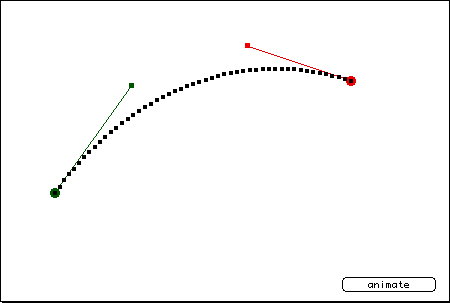
Imagine that I have a Bèzier curve that goes like this:

curve01.gif

(It's a random image I picked off the internet)

This is a Cubic Bèzier. For sake of simplicity, forget about the control points. Focus only on the starting and ending points of the curve and pretend that they're enough info to draw the curve in the picture. Imagine to draw this curve on your screen. But draw it very tiny, like it covers only 3 pixels from start to end. Can hardly call it a curve. You probably only need 2 line segments to approximate it perfectly. Makes sense? Now draw the same curve but much bigger. Maybe it paints over 200 pixels from left to right. You'll need many more than 2 line segments to approximate this curve now.

The point I want to make is that the final on-screen size of the curve is a factor to account for. From a strict mathematical point of view the curve is the same whether you draw it over 3 or 3000 pixels. But once you approximate this using straight lines, you have to factor the actual size of the image as it'll be rasterized on the screen.

The FlattenPath() function does this through the GDI rasterizer, but the blasted thing only works with integer coordinates.

I have to mimic the works of FlattenPath() while using floating point coordinates. How can I do it?

Why do you want to mimic FlattenPath? Just use something simple, like a multiple of the text size for Bezier resolution (resolution = number of segments, which also defines the final number of triangles). A safe resolution to use would probably be glyph_wdth * glyph_height, since no Bezier curve leaves the glyph's bounding box, and the worst-case scenario for a Bezier would be to cover all of the pixels in the box (just hypothetically - this will never actually happen).

Alternatively, you could always use a constant and high enough Bezier resolution, that it looks good at the highest text size you're going to draw, and it will look ok even when scaled down, even if you do end up with 1000 segments (or triangles) covering the same pixel.

Anyway, like I've been saying - you really have your work cut out for you if you decide to go ahead with tessellating the font data yourself.

If you just want to draw screen-space text, you should use GDI to draw each character into a texture, then use that as a texture atlas for drawing text. I believe this is what you originally intended, and I've also already explained how you can deal with your alpha-blending problem in my first reply.

And after investigating a bit, it seems that this is also how ID3DXFont works - it can only be used for screen-space fonts. When I mentioned tessellation, I was thinking of what D3DXCreateText does, not D3DXCreateFontIndirect - I never used any of these myself, only made some assumptions based on the samples I saw, so sorry if I misled you.

This topic is closed to new replies.

Advertisement