Texture not filling the entire render target view on resizing

Started by
14 comments, last by dave09cbank 8 years, 4 months ago

Hi

I'm trying to implement the resizing of render target when window/control is resized.

However when doing so it is not working as expected (maybe cause i'm not doing it correctly) as the rendered texture is not filling my entire render target view.

Now, when ever the window is resized, i reset my render target view and any other render target (texture) [Please see code below]


 this.ImgSource.SetRenderTargetDX11(null);

            Disposer.SafeDispose(ref this.m_RenderTargetView);
            Disposer.SafeDispose(ref this.m_d11Factory);
            Disposer.SafeDispose(ref this.RenderTarget);

            int width = (int)sizeInfo.Width;
            int height = (int)sizeInfo.Height;

            Texture2DDescription colordesc = new Texture2DDescription
            {
                BindFlags = BindFlags.RenderTarget | BindFlags.ShaderResource,
                Format = PIXEL_FORMAT,
                Width = width,
                Height = height,
                MipLevels = 1,
                SampleDescription = new SampleDescription(1, 0),
                Usage = ResourceUsage.Default,
                OptionFlags = ResourceOptionFlags.Shared,
                CpuAccessFlags = CpuAccessFlags.None,
                ArraySize = 1

            };

            this.RenderTarget = new Texture2D(this.Device, colordesc);
            m_RenderTargetView = new RenderTargetView(this.Device, this.RenderTarget);
            
            m_depthStencil = CreateTexture2D(this.Device, width, height, BindFlags.DepthStencil, Format.D24_UNorm_S8_UInt);

            m_depthStencilView = new DepthStencilView(this.Device, m_depthStencil);
                        
            Device.ImmediateContext.Rasterizer.SetViewport(0, 0, width, height, 0.0f, 1.0f);
            Device.ImmediateContext.OutputMerger.SetTargets(m_depthStencilView, m_RenderTargetView);

            SetShaderAndVertices(sizeInfo);

Also my texture data is updated from another thread via mapping the bitmap data to my render target.

Note: Texture fills the entire render target view if the mapped image is of same size as my rendered target view.

Please see screen dumps below:

1. When mapped image and render target view are of same dimensions.
[attachment=29725:Capture_SameSizeTexture.JPG]

2. When mapped image and render target view are not of same dimension
[attachment=29726:Capture_DifferentSizeTexture.JPG]

Thus the above screen-dump highlights my issue.

How would i approach this in order to resolve so that the no matter the dimensions of the mapped image my render target view is always filled with it.

Any suggestions ?

PS: Using C# , SharpDx with Directx11 and D3DImage && not using Swapchains

Thanks.

Advertisement

Does it matter if this is stretched? I guess you are rendering this texture to a quad? Can you provide some numbers to go with those images, e.g. width/height of texture and render target in the first image and width/height of both texture and render target in the second image.

Are portions chopped off in the first image (bottom and right side) or is that a normal image? Numbers will definitely help understand what's going on here and I suspect the solution will be nice and simple too.

Device.ImmediateContext.Rasterizer.SetViewport(0, 0, width, height, 0.0f, 1.0f);

The viewport sets what parts actually get rendered too, perhaps this is what is causing parts to not be rendered.

It might also be useful to see this:

SetShaderAndVertices(sizeInfo);

Interested in Fractals? Check out my App, Fractal Scout, free on the Google Play store.

thanks for the reply Nanoha.

As requested i have provided all the information below.

SetShaderAndVertices method


 protected void SetShaderAndVertices(Size rendersize)
        {
            var device = this.Device;
            var context = device.ImmediateContext;

            ShaderBytecode shaderCode = GetShaderByteCode(eEffectType.Texture);
            layout = new InputLayout(device, shaderCode, new[] {
                   new InputElement("SV_Position", 0, Format.R32G32B32A32_Float, 0, 0),
                    new InputElement("TEXCOORD", 0, Format.R32G32_Float, 32, 0),
            });

            // Write vertex data to a datastream
            var stream = new DataStream(Utilities.SizeOf<VertexPositionTexture>() * 6, true, true);

            int iWidth = (int)rendersize.Width;
            int iHeight = (int)rendersize.Height;

            float top = iWidth / 2;
            float bottom = iHeight / 2;

            stream.WriteRange(new[]
                                 {
                            new VertexPositionTexture(
                                        new Vector4(-top, bottom, 0.5f, 1.0f), // position top-left
                                        new Vector2(0f,0f)
                                        ),
                            new VertexPositionTexture(
                                        new Vector4(top, bottom, 0.5f, 1.0f), // position top-right
                                        new Vector2(iWidth,iHeight)
                                        ),
                            new VertexPositionTexture(
                                        new Vector4(-top, -bottom, 0.5f, 1.0f), // position bottom-left
                                         new Vector2(iWidth,iHeight)
                                        ),
                            new VertexPositionTexture(
                                        new Vector4(-top, -bottom, 0.5f, 1.0f), // position bottom-right
                                        new Vector2(iWidth,0f)
                                        ),
                            new VertexPositionTexture(
                                        new Vector4(top, -bottom, 0.5f, 1.0f), // position bottom-right
                                         new Vector2(iWidth,iHeight)
                                        ),
                            new VertexPositionTexture(
                                        new Vector4(top, bottom, 0.5f, 1.0f), // position top-right
                                        new Vector2(0f, iHeight)
                                        ),
                                  });
            stream.Position = 0;

            // Instantiate VertexPositionTexture buffer from vertex data
            // 
            vertices = new SharpDX.Direct3D11.Buffer(device, stream, new BufferDescription()
            {
                BindFlags = BindFlags.VertexBuffer,
                CpuAccessFlags = CpuAccessFlags.None,
                OptionFlags = ResourceOptionFlags.None,
                SizeInBytes = Utilities.SizeOf<VertexPositionTexture>() * 6,
                Usage = ResourceUsage.Default,
                StructureByteStride = 0
            });
            stream.Dispose();

            // Prepare All the stages
            // for primitive topology https://msdn.microsoft.com/en-us/library/bb196414.aspx#ID4E2BAC
            context.InputAssembler.InputLayout = (layout);
            context.InputAssembler.PrimitiveTopology = (PrimitiveTopology.TriangleStrip);
            context.InputAssembler.SetVertexBuffers(0, new VertexBufferBinding(vertices, Utilities.SizeOf<VertexPositionTexture>(), 0));

            context.OutputMerger.SetTargets(m_RenderTargetView);
        }

shader file:


Texture2D ShaderTexture : register(t0);
SamplerState Sampler : register(s0);

cbuffer PerObject: register(b0)
{
	float4x4 WorldViewProj;
};


// ------------------------------------------------------
// A shader that accepts Position and Texture
// ------------------------------------------------------

struct VertexShaderInput
{
	float4 Position : SV_Position;
	float2 TextureUV : TEXCOORD0;
};

struct VertexShaderOutput
{
	float4 Position : SV_Position;
	float2 TextureUV : TEXCOORD0;
};

VertexShaderOutput VSMain(VertexShaderInput input)
{
	VertexShaderOutput output = (VertexShaderOutput)0;

	output.Position = input.Position;
	output.TextureUV = input.TextureUV;

	return output;
}

float4 PSMain(VertexShaderOutput input) : SV_Target
{
	return ShaderTexture.Sample(Sampler, input.TextureUV);
}

// ------------------------------------------------------
// A shader that accepts Position and Color
// ------------------------------------------------------

struct ColorVS_IN
{
	float4 pos : SV_Position;
	float4 col : COLOR;
};

struct ColorPS_IN
{
	float4 pos : SV_Position;
	float4 col : COLOR;
};

ColorPS_IN ColorVS(ColorVS_IN input)
{
	ColorPS_IN output = (ColorPS_IN)0;
	output.pos = input.pos;
	output.col = input.col;
	return output;
}

float4 ColorPS(ColorPS_IN input) : SV_Target
{
	return input.col;
}

// ------------------------------------------------------
// Techniques
// ------------------------------------------------------

technique11 Color
{
	pass P0
	{
		SetGeometryShader(0);
		SetVertexShader(CompileShader(vs_5_0, ColorVS()));
		SetPixelShader(CompileShader(ps_5_0, ColorPS()));
	}
}

technique11 TextureLayer
{
	pass P0
	{
		SetGeometryShader(0);
		SetVertexShader(CompileShader(vs_5_0, VSMain()));
		SetPixelShader(CompileShader(ps_5_0, PSMain()));
	}
}

It would depend if i wish to keep aspect ratio or not.

Yes there is data chopped of in the first image as noticed by yourself.

Size for first image:
---- Display Image size (835, 626) on render target of Size(720, 576)

Size for 2nd image:
Display Image size (899, 674) on render target of Size(899, 676)

Any more information then do let me know and i will happily [provide.

Thanks.

Is 'sizeInfo' the size of your texture or of the render target, it is being used to create the render target so I assume the latter but if it is the texture size then that will explain something.

I am some what at a loss but judging by the numbers you provided it looks like the render target numbers are being used to create the view but the original texture size is being used to create everything else, certainly from the 1st image numbers as it looks like the right and bottom edge are just outside of the view. The second image numbers dispute that theory a little though :/

Interested in Fractals? Check out my App, Fractal Scout, free on the Google Play store.

i might have have not named the vaiables correctly.

top and bottom should be named as quadrant width and height as we use them in creating the vector4 vertex.

the axis are drawn with center of 0,0 with a widthand height which gives us our quadrant width(top variable ) and quadrant height(bottom variable).

Sorry for the confusion it has caused.

(-w, +h) (+w, +h)
-------------------------
| |
| |
|............ 0,0.............|
| |
| |
| |
-------------------------
(-w, -h) (+w, -h)

Hope this helps.


How would i approach this in order to resolve so that the no matter the dimensions of the mapped image my render target view is always filled with it.

Any suggestions ?

If you draw a quad that will be textured with the image straight in the projection space (-1/1x,-1/1y) it will stretch to whatever screen is, of course breaking the ratio. Since texture coordinates of verticies of the screen aligned quad do not need to change when texture dimensions change, always keep them zero/one, and reposition quad verticies in projection space, to see the image in real ratio, zoom, etc.

Projection space relation to the very screen is x positive right, y positive up, (0,0) at the center of screen, (-1.0,1.0) being left top corner, this applies to also z axis.

Read screen width/height, read image width/height and use those for pixel precise positioning, to translate into projection space.

Thanks for the information @JohnnyCode. This has been really usefuland have managed to get the resizing working (although not maintaining the aspect ratio).

Also, when you mention

Since texture coordinates of verticies of the screen aligned quad do not need to change when texture dimensions change, always keep them zero/one, and reposition quad verticies in projection space, to see the image in real ratio, zoom, etc.

does that mean i need to re-position the quad vertices if I wish to implement letter-boxing technique when re-sizing but maintain the aspect ratio ?

I did tried to set the view port but it actually doesn't draw the texture properly but rather looks as if we are zoomed into the texture like as if texture is stretched over a smaller region of the texture as shown below:

[attachment=29759:Capture_StetchedTexture.JPG]


Any ideas as to why this would happen ?


I did tried to set the view port but it actually doesn't draw the texture properly but rather looks as if we are zoomed into the texture like as if texture is stretched over a smaller region of the texture as shown below:

What you see on picture are not correctly assigned texture coordinates on respective corners (you have x txc value three times the same or something like that).

ok so whenever i change the viewport dimensions and location... Do i need to update the texture co-ordinates as well ?


Also i have added my sample text program which i have been using ... just for reference.

Download here


ok so whenever i change the viewport dimensions and location... Do i need to update the texture co-ordinates as well ?

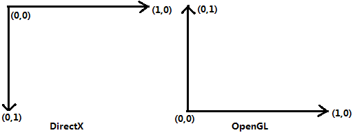
No you don't, just map complete texture onto the quad, this is what texture space looks like

20100531_DX_OpenGL.png

This topic is closed to new replies.

Advertisement