using World transform to move objects stored on a single vertex buffer

Started by
10 comments, last by galop1n 6 years, 5 months ago

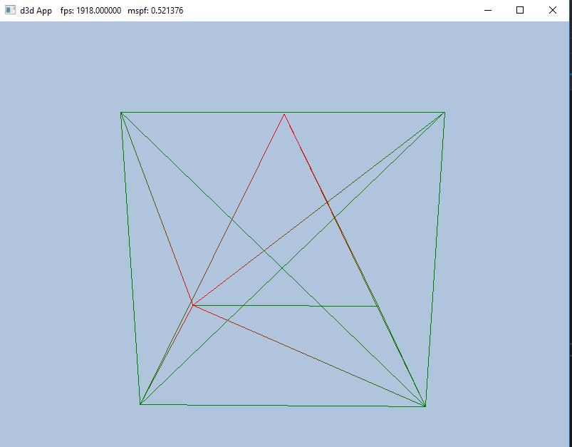
I'm currently learning how to store multiple objects in a single vertex buffer for efficiency reasons. So far I have a cube and pyramid rendered using ID3D12GraphicsCommandList::DrawIndexedInstanced; but when the screen is drawn, I can't see the pyramid because it is drawn inside the cube. I'm told to "Use the world transformation matrix so that the box and pyramid are disjoint in world space".


Can anyone give insight on how this is accomplished? 


     First I init the verts in Local Space


std::array<VPosData, 13> vertices =
    {
        //Cube
        VPosData({ XMFLOAT3(-1.0f, -1.0f, -1.0f) }),
        VPosData({ XMFLOAT3(-1.0f, +1.0f, -1.0f) }),
        VPosData({ XMFLOAT3(+1.0f, +1.0f, -1.0f) }),
        VPosData({ XMFLOAT3(+1.0f, -1.0f, -1.0f) }),
        VPosData({ XMFLOAT3(-1.0f, -1.0f, +1.0f) }),
        VPosData({ XMFLOAT3(-1.0f, +1.0f, +1.0f) }),
        VPosData({ XMFLOAT3(+1.0f, +1.0f, +1.0f) }),
        VPosData({ XMFLOAT3(+1.0f, -1.0f, +1.0f) }),

        //Pyramid
        VPosData({ XMFLOAT3(-1.0f, -1.0f, -1.0f) }),
        VPosData({ XMFLOAT3(-1.0f, -1.0f, +1.0f) }),
        VPosData({ XMFLOAT3(+1.0f, -1.0f, -1.0f) }),
        VPosData({ XMFLOAT3(+1.0f, -1.0f, +1.0f) }),
        VPosData({ XMFLOAT3(0.0f,  +1.0f, 0.0f) })
  }

Then  data is stored into a container so sub meshes can be drawn individually


SubmeshGeometry submesh;
	submesh.IndexCount = (UINT)indices.size();
	submesh.StartIndexLocation = 0;
	submesh.BaseVertexLocation = 0;

	SubmeshGeometry pyramid;
	pyramid.IndexCount = (UINT)indices.size();
	pyramid.StartIndexLocation = 36;
	pyramid.BaseVertexLocation = 8;


	mBoxGeo->DrawArgs["box"] = submesh;
	mBoxGeo->DrawArgs["pyramid"] = pyramid;


Objects are drawn


mCommandList->DrawIndexedInstanced(
		mBoxGeo->DrawArgs["box"].IndexCount,
		1, 0, 0, 0);

	mCommandList->DrawIndexedInstanced(
		mBoxGeo->DrawArgs["pyramid"].IndexCount,
		1, 36, 8, 0);


Vertex Shader


cbuffer cbPerObject : register(b0)
{
	float4x4 gWorldViewProj; 
	
};


struct VertexIn
{
	float3 PosL  : POSITION;
    float4 Color : COLOR;
};

struct VertexOut
{
	float4 PosH  : SV_POSITION;
    float4 Color : COLOR;
};

VertexOut VS(VertexIn vin)
{
	VertexOut vout;
	
	// Transform to homogeneous clip space.
	vout.PosH = mul(float4(vin.PosL, 1.0f), gWorldViewProj);
	
	// Just pass vertex color into the pixel shader.
    vout.Color = vin.Color;
    
    return vout;
}

float4 PS(VertexOut pin) : SV_Target
{
	
    return pin.Color;
}


Untitled.png

Advertisement

Where's your code that makes the worldviewproj matrix?  Where's your code that makes the world matrix?  Do you understand what the world matrix does?  Do you understand what the view matrix does?  Do you understand what the Projection matrix does?

-potential energy is easily made kinetic-

Can anyone at least point me in the right direction?

20 hours ago, Infinisearch said:

Where's your code that makes the worldviewproj matrix?  Where's your code that makes the world matrix?  Do you understand what the world matrix does?  Do you understand what the view matrix does?  Do you understand what the Projection matrix does?


    //Initialization 
    XMFLOAT4X4 mWorld = MathHelper::Identity4x4();
    XMFLOAT4X4 mView = MathHelper::Identity4x4();
    XMFLOAT4X4 mProj = MathHelper::Identity4x4();


// Build the view matrix.
    XMVECTOR pos = XMVectorSet(x, y, z, 1.0f);
    XMVECTOR target = XMVectorZero();
    XMVECTOR up = XMVectorSet(0.0f, 1.0f, 0.0f, 0.0f);

    XMMATRIX view = XMMatrixLookAtLH(pos, target, up);
    XMStoreFloat4x4(&mView, view);


    XMMATRIX world = XMLoadFloat4x4(&mWorld);
    XMMATRIX proj = XMLoadFloat4x4(&mProj);
    XMMATRIX worldViewProj = world*view*proj;

	
	// Update the constant buffer with the latest worldViewProj matrix.
	ObjectConstants objConstants;
    XMStoreFloat4x4(&objConstants.WorldViewProj, XMMatrixTranspose(worldViewProj));


World matrix is used when converting coordinates from local space to world space.  

View Matrix is used when converting coordinates from world space to camera space.

Projection Matrix is used to map 3D coordinates on a 2D plane. 


Think I understand these concepts well enough, I'm just not sure how to apply this to only the first 8 or last 5 vertices of the single vertex buffer. 

When you trigger a draw call, you provide a base vertex location, and a start index location. If you want to draw a cube and a pyramid from the same vertex and index buffer, you just have to issue two draw calls with the proper triangle count and offsets to the wanted geometry.

If you want to draw both the cube and the pyramid in a single draw call, considered a single geometry, you will have to do something like skinned geometry, provide a bone index in the vertices,  and read that in the vertex shader to index into an array of world matrix.


Also, i would advocate from describing everything as matrices but as transformation because It is not mandatory to be a matrix. As for an example, a world transformation could be a Quaternion for orientation, a vector3 for translation and a scalar for scale ( no, don't do non uniform scale, it is bad ! ).


5 hours ago, galop1n said:

When you trigger a draw call, you provide a base vertex location, and a start index location. If you want to draw a cube and a pyramid from the same vertex and index buffer, you just have to issue two draw calls with the proper triangle count and offsets to the wanted geometry.

If you want to draw both the cube and the pyramid in a single draw call, considered a single geometry, you will have to do something like skinned geometry, provide a bone index in the vertices,  and read that in the vertex shader to index into an array of world matrix.


Also, i would advocate from describing everything as matrices but as transformation because It is not mandatory to be a matrix. As for an example, a world transformation could be a Quaternion for orientation, a vector3 for translation and a scalar for scale ( no, don't do non uniform scale, it is bad ! ).


The concept makes sense to me, but I still don't understand where to place this transformation in my code. 

Look at the first few lines of your vertex shader.  Also look at the code that makes that constant buffer.

-potential energy is easily made kinetic-

The "world" part of a WorldViewProj describes the objects position, rotation and size.

To make different objects not be all in the same place, instead of a single gWorldViewProj in the shaders, you would need a seperate "world" for each object (or a seperate gWorldViewProj if you wish to do the combining of world,view,projection in the cpu like you are at the moment)

You could either have an array of them inside a constantbuffer, or have a structurebuffer. If you are using executeindirect you dont need an array of them as seen by the vertexshader as you can use it to change the start of your constant buffer view to a different piece of data in a single larger buffer which is an array of all of them.

Your vertex could store its objectnumber so it can choose the correct array element in the vertexshader, but thats not ideal if you wanted to draw multiple of the same object in different positions in the world.


As this is DX12 you could solve the problem of transmitting the objectnumber to the gpu without imbedding it in a vertex by using a executeindirect instead of a drawindexed as it is tailor made to draw multiple different objects in a single draw

Executeindirect can change values in the rootsignature with each draw it issues so it could either be used to pass the objectnumber as a rootconstant or even better can change a single gWorldViewProj constantbufferview and not need an array in the vertexshader and this would be faster.

See the D3D12ExecuteIndirect sample https://msdn.microsoft.com/en-us/library/windows/desktop/mt186624(v=vs.85).aspx

That sample does this very thing by having a different position for each object by changing the constantbufferview to start at a different element in a bigger buffer which is basically an array of them.

No one said it so i will say it : "If you are not yet an expert at DX11 or if you don't know why your application is in the 1% that would benefit from DX12 explicitely, then you should stick to DX11".

DX12 is not a replacement for DX11, it is an edge case scenario just like Vulkan is an edge case scenario to OpenGL.

You are struggling with rendering two objects, DX12 is not for you for at least many years of intense DX11 usage.

9 hours ago, Infinisearch said:

Look at the first few lines of your vertex shader.  Also look at the code that makes that constant buffer.

I get that I can create new world and MVP matrices to separately  describe the positions, but it still doesn't solve the problem of how I tell the shader to use MVPA on the cube and MVPB on the pyramid.

This topic is closed to new replies.

Advertisement