Character Solver

Started by
13 comments, last by D956 6 years, 4 months ago


So right now for my character solver I compute the time of impact of a character AABB and convex polygons using an algorithm based on "Robust Continuous Collision Detection Between Arbitrary Polyhedra Using Trajectory Parameterization of Polyhedral Features" by J.M.P van Waveren (link)

Doom 3 uses this for all of it's collisions so it never has to deal with penetration. This seems undesireable for a couple of reasons so I've decided I'm going to switch to a position solver instead. After some googling I came across Erin Catto's 2014 GDC presention "Understanding Constraints" (link) where he briefly describes how his character solver works. I've written a simple C program (attached to this post) to play around with these concepts and I have some questions that hopefuly I will be able to get answered here.

Keys for the test program:

  • ESC - quit
  • r - reset
  • s - step
  • 1-8 - switch to setup 1-8

Here's how I intepret the algorithm:

  • Let's call the current position of the character the 'initial position'. This position never changes during the algorithm.
  • Let's call the position we are trying to move the character to the 'target position'. This position also never changes during the algorithm.


  1. Scan the environment for overlap with the capsule at the initial position and construct a list of contact planes.
  2. Perform a plane solve on the target position to get the first solve position.
  3. Perform a shape cast from the initial position to the solve position. Move to the first hit point and collect new contact planes there. Add these new planes to the list.
  4. Perform a plane solve on the target position to get the next solve point.
  5. If the distance between the new solve point and the old one is within some epsilon, we are done. Otherwise go back to step 3.

Plane solve code:


vec3_t p = target_position;
vec3_t a = p + local_capsule_a;
vec3_t b = p + local_capsule_b;

for(uint32_t i = 0; i < max_iter; i++)
{
  vec3_t last_p = p;

  for(uint32_t j = 0; j < plane_count; j++)
  {
    const plane3_t &plane = planes[j];

    float d1 = point_distance(plane, a);
    float d2 = point_distance(plane, b);

    float dist;
    if(d1 < d2)
      dist = d1;
    else
      dist = d2;

    dist -= capsule_radius;

    if(dist < 0.0f)
    {
      p -= dist * plane.n;
      a = p + local_capsule_a;
      b = p + local_capsule_b;
    }
  }

  vec3_t delta = p - last_p;
  if(dot(delta, delta) < epsilon)
    break;
}

solve_position = p;

Couple of issues:

1. Is this interpretation correct?
2. In the test program I am only adding one new plane per shape cast, is there a reason to collect more (all touching planes)?
3. In the test program I am using the segment planes directly. In 3D I would directly use the polygon planes. If I use the direction from the closest point on the segment to the circle centre I get into situations like this, where the character ends up away from the collision geometry:
3Mv6OSk.png
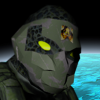
4. If I naively add all overlapping planes during step 1 I get into sitations like this:
l8YUhaN.png
The green circle is at the source position. Step 1 will find both planes and the character will end up in the corner, not touching either segment. In the test program I solve this problem by clearing the plane list after step 2, but this is insufficient as I also need to select the proper planes after a shape cast. I can think of some approaches to solving this problem, but instead of experimenting right away, I'd like to know how other people have solved this. What is a good way to determine which planes to actually use?


test.c

Advertisement
3 hours ago, D956 said:
  • Let's call the current position of the character the 'initial position'. This position never changes during the algorithm.

together with

3 hours ago, D956 said:
  • Scan the environment for overlap with the capsule at the initial position and construct a list of contact planes.

and together with

3 hours ago, D956 said:

1. Is this interpretation correct?

Your interpretation is at least at one point not the same as the algorithm outline on slide page 60 and your own implementation, because the algorithm does not inspect the initial position. Instead it inspects a series of target positions, starting with the initial position being the desired target position.


3 hours ago, D956 said:

2. In the test program I am only adding one new plane per shape cast, is there a reason to collect more (all touching planes)?

The algorithm / implementation does not really collect planes at all but iteratively effects the position by considering one wall after the other. Other than this wording stuff ... I don't understand your question.


3 hours ago, D956 said:

3. In the test program I am using the segment planes directly. In 3D I would directly use the polygon planes. If I use the direction from the closest point on the segment to the circle centre I get into situations like this, where the character ends up away from the collision geometry:

This is because the algorithm / implementation considers all walls being infinite planes. But walls are just plane segments, i.e. they have a beginning and an end. Hence computing just a distance from the plane is not sufficient (at lest when dealing with outside corners); you have to consider the distance from the segment instead.

To illustrate this: Let's say we use a 2D top view on the scene. Then the wall can be described by a line segment between its beginning at position b and its ending at position e as

          w(k) := b + k * ( e - b )   with  0 <= k <= 1

After computing the collision point c with the plane like before, you can solve the above equation for k, so that

         b + k * ( e - b ) == c

The collision point is on the segment if and only if the resolved k is within its definition range 0 <= k <= 1. Otherwise the collision happens "in the air" apart from a wall corner. However, the capsule may still collide because it has a given size, but the collision point so far is just - well - point. For collisions detection with a corner you just need to check whether one of the corner points (i.e. b and e) is within the collider volume.


BTW: Using an AABB is not necessarily the easiest way to go.


The way I am reading the slides is that the algorithm has two parts to it. One part collects contact planes using a shape cast and the other part is a plane solver (NGS) that tries to find the closest point (solve point) to the target position whilst satisfying the plane constraints.

Part one is described on page 59:

Quote

Here's how the algorithm works. I first scan the environment for any overlaps. These used to create a list of collision planes. I then move the character to the target point and then apply NGS until the character is not moving much. This is solver point1. Then I perform a sweep from the start point to solve point1. Any new collision planes are added to the list. Again I move the character to the target point and then apply NGS to the new set of collision planes to get solve point2. I keep repeating this process until consecutive solve points are close together.

Part two, what you are referring to, is described on page 60:

Quote

  So how does the plane solver work? The input data to the character solver is the target position and the constraint planes. We do not need the current position of the character! The current position of the character is only used to gather contact planes. I can now state the job of the character solver: find the position closest to the target position that satisfies the contact plane constraints. We can use a simple NGS solver to solve this. It is incredibly simple because the mass doesn't matter when there is only one movable object that doesn't rotate. Also, the constraints are all linear. With just a couple planes we can compute an exact solution. But as we get many contact planes this becomes more difficult, so I use an iterative solve to get an approximate solution. Also, we don't need an exact solution, we just need a valid solution.

Quote

This is because the algorithm / implementation considers all walls being infinite planes. But walls are just plane segments, i.e. they have a beginning and an end. Hence computing just a distance from the plane is not sufficient (at lest when dealing with outside corners); you have to consider the distance from the segment instead.

To illustrate this: Let's say we use a 2D top view on the scene. Then the wall can be described by a line segment between its beginning at position b and its ending at position e as

          w(k) := b + k * ( e - b )   with  0 <= k <= 1

After computing the collision point c with the plane like before, you can solve the above equation for k, so that

         b + k * ( e - b ) == c

The collision point is on the segment if and only if the resolved k is within its definition range 0 <= k <= 1. Otherwise the collision happens "in the air" apart from a wall corner. However, the capsule may still collide because it has a given size, but the collision point so far is just - well - point. For collisions detection with a corner you just need to check whether one of the corner points (i.e. b and e) is within the collider volume.

I know. "segment_closest_point" in my test program actually accounts for this by returning a vertex of the line segment if the proper barycentric coordinate is negative.

Quote

BTW: Using an AABB is not necessarily the easiest way to go.

I guess I wasn't clear enough. I am currently using an AABB and it is working fine with static geometry. Except that now I want to add dynamic rigid bodies. Realising I will have to deal with penetration anyway, I decided to ditch this method and change to a position-based solver using a capsule shape like the one described by Erin Catto in the presentation above.

One solution to issue 4 is to collect polygons instead of only their planes. Then, during the position correction step I find the polygon with the smallest penetration that is still in front of the capsule and move the capsule in front of it's plane.

Of course this leads to other problems...

Catto doesn't mention any of this though, so I wonder if there's a trick to the algorithm so I only have to use planes.


The algorithm works by applying correction on-the-fly on each found penetration. That means that a penetration with the current plane is found, the current position and hence the penetration depth and hence the correction value will depend on all already made corrections. I don't understand why you are speaking of "collecting planes / polygons", because that does not happen anywhere within the algorithm.

Coming back to the problem of overcompensation when colliding with (outside) corners: The problem exists because there are two walls that both contribute to the correction that would better be only one. This is, as already written above, because the algorithm deals with infinite planes only. Now, let's say that your implementation is able to distinguish collisions with planar pieces of a wall and with wall corners (see another post above). If a "planar collision" is on then work on it as usual. But if a "corner collision" is on then construct an imaginary plane that passes through the corner and has its normal computed as average of the normals of the both adjacent planes / walls.

With respect to the structure of the original algorithm, the solution described above will do an adapted correction when the collision with the first of both planes is detected, and it will do no further collision when the second plane is current because there is no longer a collision then.

If you think further then you'll see that the solution above is kind of a generalization. I.e. it would work well even if it would be applied on a planar piece of the wall, because averaging two times the same normal results in the normal itself, of course.

Thank you very much for replying!

I've been googling some more and came across documentation for the DigitalRune project (link). They also use a capsule shape and do a similar plane solve as Erin Catto describes. This is how they describe their position correction:

Quote

Slide: The basic routine in our character controller is called a slide. It takes a desired position and computes a valid, non-penetrating position near the desired position like this:

The capsule is set to the desired positions and we detect all intersections. The collision detection returns all contacts at the desired position, including contact positions, contact normal vectors and penetration depths. Each contact indicates that we have moved into a solid object - we have reached a limit of the allowed movement space.

For each contact found we store a bounding plane that represents that movement limit. If the capsule touches a wall, the bounding plane is parallel to the wall surface. If the capsule touches an object like a sphere, the bounding plane is parallel to the tangential plane at the contact point. All bounding planes together limit the allowed space in which the capsule can move.

Now, that we have a description of the allowed space in which the character can move, we compute the allowed position closest to the desired position. We do this by a simple iterative process: If we have no bounding planes or the desired position is in front of all bounding planes, we are done. If the desired position is behind a bounding plane, we project the position onto the surface of the bounding plane. The new position is checked against the next plane. If it is behind the plane it is projected onto the surface. The new position is checked against the other planes, and so forth. This is done in a loop until we have found an allowed position in front of all bounding planes.

Once, we have found the new position, we set the capsule to the new position and detect all intersections. It is possible that we find new bounding planes that we add to the set of existing bounding planes. We repeat the process above until we have a new position that does not violate any bounding plane.

This is very similar to Erin Catto's approach, except that Catto adds a "shape cast".

So the game code decides it wants to move the player from the "initial position" to the "target position", then:

DigitalRune algorithm:

  1. Clear the plane list.
  2. Detect collisions at the target position and collect bounding planes. If we don't find any collisions we are done.
  3. Plane solve to get a new target position.
  4. Go back to step 1.

Erin Catto's algorithm as I now interpret it:

  1. Clear the plane list.
  2. Detect collisions at the target position and add bounding planes to the plane list.
  3. Plane solve to get the first solve position (target position -> solve position).
  4. Clear the plane list.
  5. Perform a shape cast from the initial position to the solve position.
  6. Set the target position to the shape cast position.
  7. Detect collisions at the target position and add bounding planes to the plane list.
  8. Plane solve to get a new solve position (target position -> solve position).
  9. If the distance between the new solve position and the old one is within some epsilon we are done. Otherwise go back to step 4.

Erin Catto has as a first step "I first scan the environment for any overlaps". I assume he means the target position.

It seems the plane solver is pretty much the same in both algorithms.

I have attached a new test program. ESC to quit, arrow keys to move the circle. Seems to work fine, except I am currently not doing the shape cast. I guess the shape cast is there in case the plane solver moves past an object/polygon that wasn't detected during steps 2 & 7.

As for the overcompensation; I will look into using normal averaging. Right now I simply use the normalised direction from the closest point on the segment to the circle centre as normal, which seems to work fine.

Now I just have to implement it in my 3D game/engine and see how well it works there.

test2.c

It's possible to use a much simpler algorithm for characters. Catto's algorithm is more complicated and overkill, intended to be able to solve the entire physics timestep continuously.

A simpler Seidel solver can work for characters, along with something akin to Conservative Advancement.

I found this post by you: https://forums.tigsource.com/index.php?topic=51779.msg1203653#msg1203653

Isn't this pretty much Catto's algorithm outlined above?


Oh my mistake! I thought you were referring to "bilateral advancement", and didn't realize you were linking to a completely different algorithm. Yes, Catto is talking about the exact same thing I was on tigsource forums :)

To clarify, I think you are on the right track by using a position level plane solver. They are really simple and efficient. Also, using a rounded shape like sphere/capsule is another good choice for characters.

It would be wise to let your algorithm handle the case of multiple simultaneous planes. Since the plane solver presses the character along a given plane normal, which does not necessarily coincide with the character's previous path of motion, it is completely possible to "back up" into a configuration hitting multiple simultaneous planes.

Gathering up planes is a matter of implementation. One idea would be to use Conservative Advancement (which will be very efficient if your capsule cannot rotate at run-time, and only translates) to find a TOI. At the TOI you should have a plane normal (e.g. from a previous GJK call, or perhaps from some collision detection algorithm; it's up to you). Press away from the plane to create a numeric buffer for subsequent Conservative Advancement calls, and zero out the velocity along the plane normal. Look for a colliding configuration, and then carry on with the remaining velocity if all is OK.

Thanks for your advice. I will experiment and see what works best. Right now I'm only doing discrete collision detection using GJK and then plane solve. The next step is to add conservative advancement, which should be very straightforward. I'll also have to add a separating axis test for when the capsule's segment penetrates a polygon/object.


This topic is closed to new replies.

Advertisement