Height map terrain + discontinuities

Started by
14 comments, last by frob 6 years, 4 months ago

I want to create terrain that has sharply defined features, but still has the flexibility of a height map. Though a height map must be defined by a grid, I don't want to terrain to look like a grid. All my previous approaches to this problem tend to look like grids, so now I'm aiming to allow for completely arbitrary discontinuities in the height map. It should be possible to split a cell of the grid between two or more elevations and along curved boundaries. The discontinuities should be independent of the height map grid. Here is a hand-made illustration of the kind of terrain we're aiming for:

GridSpiral.jpg.923d40e6527d89e9aadfc67572d8c19f.jpg

On the left is a curve of discontinuity that has been drawn onto a height map grid. On the right is a rendering of height map terrain that has been split along the same discontinuity curve. Wherever a discontinuity is found, the terrain represents a difference in elevation by a vertical wall instead of the usual slope. The idea is to get an automated system for putting this sort of terrain into a game.

I have considered allowing the discontinuities to be an unrestrained set of line segments with floating-point 2D vertices. We'd have total freedom to draw any discontinuities we could imagine, such as splitting a single grid cell into a dozen pieces. This introduces many complexities, such as forcing us to use procedural triangulation to determine how each cell should be rendered. Here is a link to a pdf guide to the Ear Clipping algorithm which we might use for this triangulation: Triangulation By Ear Clipping

It also makes navigating the terrain tricky. At a minimum we need to determine if one of the player's moves would cross a discontinuity. That in itself is not too hard, but we wouldn't want the player to be stopped dead just by brushing a discontinuity. We want the player to slide along these barriers when appropriate, and the math behind doing that is not at all obvious. We also need a way for computer-controlled enemies to navigate this world, perhaps by automatically generating a navigation mesh.

Perhaps the problem should be simplified by restricting the discontinuities in ways that have no significant impact on the resulting terrain. We don't particularly want a cell to be split into a dozen pieces, so maybe there should be a limit to how many discontinuities can pass through a single cell. We might be limited to certain vertices within each cell, such as a vertex on each corner, a vertex somewhere on each edge, and a 9th vertex floating somewhere in the interior of the cell. With that sort of restriction, triangulation should be greatly simplified.

What sort of algorithms and approaches would you use to create this effect? Are there any other ways to simplify the problem?

Advertisement

I think all of those problems have already been solved.

Automatic navigation meshes are covered by all kinds of examples online, and they work well especially if you add a margin around the areas. Capsule collision shapes allow easier physics sliding along the boundaries and slopes. There really shouldn't be an issue with multiple discontinuities in the cell, unless it interferes with some other aspect of your system.


5 minutes ago, frob said:

I think all of those problems have already been solved.

Does that mean you'd go ahead with implementing the full unsimplified plan, ear clipping and all? All of this is sufficiently easy that there's no reason to look for an easier way?

Depends on the skill level and experience of the developers.

For me personally, I would have no problem implementing that as described:  Start with a regular grid for your terrain mesh. Subdivide along those curves -- it doesn't need to be that specific algorithm as there are many good ones -- and avoid T-junctions which cause cracks. Adjust heights and add triangle strips along the wall edges. Create a 2D navigation mesh for both player and AI by starting with your curve image, expanding a margin around the (a one-pass kernel operation), and using that image or map directly as a 2D grid. Maybe adjust the image around the ends of lines if you want to enable a slight hop over them. Add object footprints as necessary for world items, again use that same image or map for the starting point to add object footprints in 2D.  

I've done each of those tasks before on various projects, none are particularly difficult if you're already comfortable manipulating meshes and grids. Did I miss any steps of your project?

If there are any steps in there you (or the people building the system) don't fully understand it will take reading, but all of them are solved problems.

Incidentally, a quick image from a demo tool from about 20 years ago. Polygonal cuts without cracks has been solved for decades.This demo tool happens to divide in regular triangles, but you can cut along any arbitrary line. I mouse-drew your path, but you could do it along any length you want, not just a regular grid.

TIN_subdivision.PNG.b1e4a10c6dabb2ce5632c3fe6b736bd5.PNG

35 minutes ago, frob said:

Subdivide along those curves -- it doesn't need to be that specific algorithm as there are many good ones -- and avoid T-junctions which cause cracks.

This seems to be recommending something quite different from ear splitting. It looks more like a quadtree based implementation. At least that's what I think of first when I see the word "subdivide" and the image you provided. For example, I've created an illustration showing a single grid cell that has been subdivided by quadtree around a curve.

CurveSubdivide.jpg.87095df1171d379250b3091048f98478.jpg

The curve is in blue. The black lines are the new squares that have been inserted to subdivide the cell. The gray lines represent the special triangulation that we'd do to eliminate T-junctions. I've included additional subdivisions to make sure that no square is subdivided more than one level deeper than its neighbors so we only have to deal with a few possible types of T-junction.

This raises a question: How far do we subdivide? The algorithm could subdivide forever and never exactly reach the curve. Even just trying to get close to the curve would seem to cause an explosion in the number of triangles in the mesh. Using diagonals across the corners of the squares helps, but even in the image you supplied it looks like jagged curve following a grid.

54 minutes ago, frob said:

Create a 2D navigation mesh for both player and AI by starting with your curve image, expanding a margin around the (a one-pass kernel operation), and using that image or map directly as a 2D grid.

I was planning to store the curves as line segments, but this seems to be suggesting we use a raster image exclusively. At least I've only ever heard of kernel operations being applied to rasters. Rasters are enticing in their simplicity, but I worry that we'd have no way to determine the slope of curve, and I was hoping to use the slope of the curve to implement the player sliding along walls.

Perhaps the idea is to use the capsule collision shape to enable sliding even without any slope information for the walls. But in that case, wouldn't we want to avoid expanded margins? It seems the point of margins is so we can do collisions against just the centers of moving objects instead of having to worry about collision shapes, but we'll want to detect collisions before they reach the center of the object in order to do angle calculations. Here's an illustration:

CircleCollision.jpg.e9606e819431392a1de4073342cad0bf.jpg

The blue curve is the wall. The black curve is the capsule collision shape that is colliding with the wall. The blue arrows show the direction from the center to the detected collisions. The red arrow is the direction the player is trying to move. The black arrow is the actual movement, perpendicular to the collision direction that's closest to the player's intended movement so we avoid going through the wall while still making progress in roughly the player's intended direction. Does this sound right?

1 hour ago, frob said:

Did I miss any steps of your project?

That seems to cover everything, but more details are always appreciated.

4 hours ago, Outliner said:

It looks more like a quadtree based implementation.

As I wrote:

5 hours ago, frob said:

This demo tool happens to divide in regular triangles, but you can cut along any arbitrary line.

There have been tools and algorithms to build TIN's for over 40 years, and T-joint preventing algorithms for at least 30 of those years. It takes slightly more work to modify the mesh, but still very easy if you are comfortable with mesh manipulation.

7 minutes ago, frob said:

This demo tool happens to divide in regular triangles, but you can cut along any arbitrary line.

What does that mean exactly? It's nice that the tool allows that, but it would be even nicer if we had access to that tool or the algorithm that it uses. How does it allow us to cut along any arbitrary line? Are we talking about using regular triangles to approximate arbitrary lines? Does the algorithm that it uses have a name?

9 minutes ago, frob said:

There have been tools and algorithms to build TIN's for over 40 years.

It's nice to know how old algorithms are, but it would be more useful to know the names of the algorithms so we can look them up and get details.

I'm very sorry, I forgot that this was in For Beginners.

I thought this was in the General/Gameplay forums, where people are generally assumed to have more knowledge and experience.  When you wrote lines like "the terrain we're aiming for", "We'd have total freedom", and other "we" statements it seemed you were working with an experienced group. As it is for beginners, I'll try to keep it simple. Everyone starts somewhere.

Going through each. Apologies if something feels too basic or too advanced, I'm not sure what skill levels you are at.

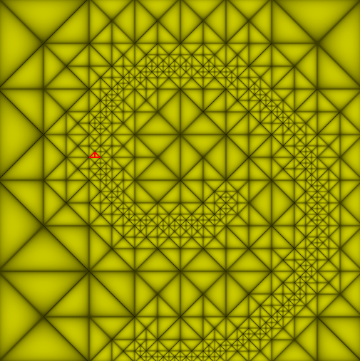
Staring with a mesh for the terrain, you can begin with whatever polygonal mesh you want, usually people use triangles on a regular grid. With the shape you're describing you will probably not use a regular mesh. You can find many different data structures by searching for "triangular irregular mesh", there are many different structures with their own pros and cons.  

It looks like you've already got the point about T-junctions. They tend to introduce small holes and gaps.  These are easy to avoid and there are many different techniques. Subdividing a triangle has a few approaches, usually either a subdivision in the middle breaking it into three pieces, or dividing any side of the triangle. Another approach is to turn an edge into multiple fans, but the math is a bit more complex. There are different reasons to split on either side versus splitting in the center, and some algorithms do both.  For search terms try: triangle surface loop subdivision algorithms, triangle mid-edge subdivision algorithms, triangular mesh butterfly algorithms, and triangular mesh sqrt(3) algorithms. There are many others developed over the decades, but those should help explain how it is done and the reasons to pick each one.  Some of the algorithms are extremely simple and produce good results quite rapidly, some produce fewer polygons, some produce denser polygons useful for sub-pixel effects.

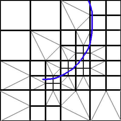
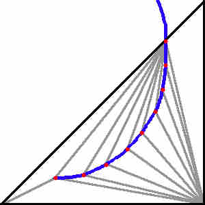
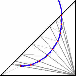
I know the image I posted used a regular grid, and I'm wondering if it would have been better not to post that.  Again, you can use any arbitrary slice.  I've seen tools that approximate a curve by using a triangle fan with many narrow steps. They step along the curve to find points along it within the triangle, then use those points to build the dense fan, then run a check to correct for T-junctions.

You ask how far to subdivide, and that one really is up to you.  Except for straight parametric lines, a parametric curve can never be perfectly represented in polygons.  If you split on an irregular pattern you can approximate the curve as much as you'd like. I noticed the Ear Clipping routine you posted doesn't work with a parametric curve but with known polygon points. In theory you could continue subdividing a curve with multiple vertices per pixel. There are algorithms that will do that, called subdivision surfaces, useful when looking at sub-pixel accurate effects.  They're rarely used to the sub-pixel level in games except in rare cases with lighting shaders and such, but common in movies for various smooth surface effects.  Consider a sphere as a good example: A sphere may be broken down as 20 points, 50 points, even 10000 points, but current rendering technology with pixels doesn't render a sphere as a smooth curve. You may use sub-pixel accuracy in order to get the pixel to have highly accurate coloration or anti-aliasing, but ultimately it is still a square pixel and not a curve.

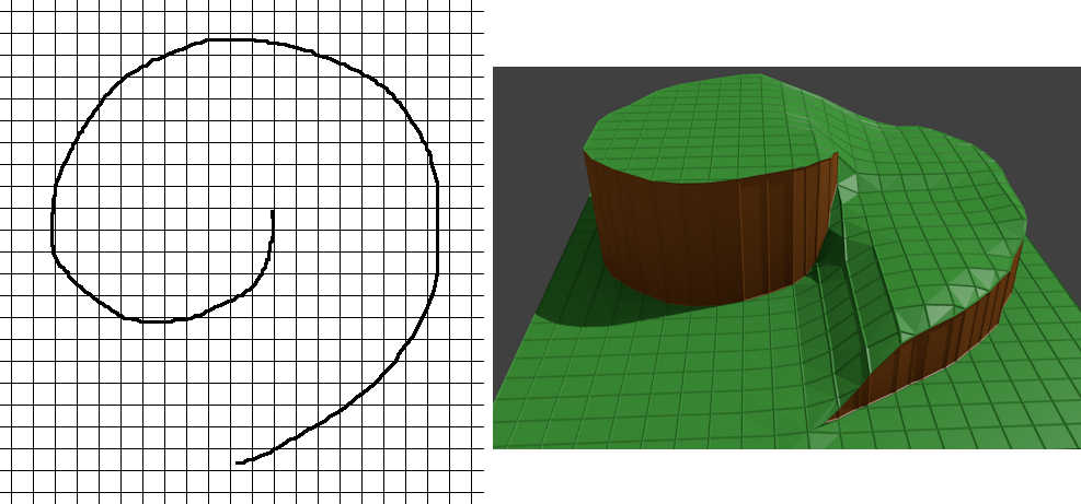
Once the polygons are simplified on the x/z or x/y plane (depending on what axis you are using) then adding height is straightforward.  Since you've already divided the points along the boundary, you duplicate the points along the boundary -- once for the upper level and once for the lower level -- and walk along the two edges with a triangle strip to make the walls. 

With that done, you've got any arbitrary curve as you described, with as much high detail or low detail as you would like.


Regarding the navigation mesh, the question comes back to the curve and the navigation engine you are using.  If you are working with a true parametric line then it might be easy or difficult to turn into a collision shape based on the system.  If your system supports parametric surfaces then use it directly. Otherwise, if the system requires line segments or polygons, you are back to the same issue of how much to subdivide. Turning a curve into line segments cannot realistically be done forever, at some point the line must be close enough.  If you're working from an image then you can go up to the individual pixels of the image.  Navigation meshes are typically very coarse, but you can make it as dense as you'd like. Dense grids tend to be more processing work for pathfinding, so consider another pass to remove unnecessary internal points if you're using a polygonal navigation grid.

The comment about processing the terrain navigation as an image with a kernel was one way that many navigation meshes work. Many games use a simple 2D image and encode different areas with different colors or attributes. While it is easy to think of them as colors, the image could hold any information as bits. Perhaps one bit to indicate it can be walked, another to indicate swimming, another to indicate climbing, another to indicate a non-jumping zone, another to indicate slow movement, whatever is needed.  Sometimes they have multiple flags. Sometimes they're combined with other systems, like an audio system to indicate walking on wood or leaves or gravel.  Navigating on a 2D image this way is easy to compute by mapping the character coordinates into an image coordinate and checking the individual cell or the neighbors to the cell.

I mention expanded margins around the barriers/walls because they are commonly used as a safety to prevent passing through a barrier. Performing continuous swept volume tests will detect if you would have passed through the wall, but those are fairly expensive mathematically. It is generally easier to make barriers thick enough that they won't pass through due to numeric drift or big time steps. 


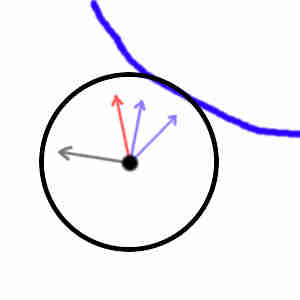
Regarding sliding along a wall, I'm not sure what the algorithm is named or if it even has a name.  Basically if you're against a wall or boundary you want to subtract the motion that would push you through the wall. Start by finding the normal of the boundary so you know what way is out. Multiply that direction by the dot product of your velocity and the direction, that will give you the amount of motion that is headed toward the wall.  What remains is the part of the speed headed in the right direction.  In math terms: velocity -= wallNormal *  dotProduct(velocityNormalized, wallNormal).   If you want to preserve speed, which may not feel natural in your game, set the velocity magnitude equal to the original magnitude.  You may also want to do it in two steps, one phase to approach directly to the contact point, then subtract that from your remaining distance; the second phase would use the remaining portion to slide against the wall.


Again, I'm very sorry for not paying attention that this was in For Beginners.  Usually there is someone (often moderators like myself) who reminds people to stay on topic in For Beginners and keep it directed to the topic. 

Better?

13 hours ago, frob said:

You can find many different data structures by searching for "triangular irregular mesh", there are many different structures with their own pros and cons.

That search gives many results and most of them don't seem to be relevant. I'll take your word for it that useful results are in there, but perhaps an example of the sort of thing we're looking for would make it easier to spot the good results.

13 hours ago, frob said:

I've seen tools that approximate a curve by using a triangle fan with many narrow steps. They step along the curve to find points along it within the triangle, then use those points to build the dense fan, then run a check to correct for T-junctions.

It's a bit confusing that we're both building triangles and finding points within "the triangle". If we're talking about a whole fan of triangles, then which triangle is "the triangle"? From the sound of it, I'm guessing that we're building the triangle fan inside another larger triangle. Perhaps a picture is worth a thousand words. Is this the kind of thing we're talking about?

TriangleFanTriangle.jpg.fcec11493f7b4d07b4dcec11239758b4.jpg

The curve is in blue. "The triangle" is in black. The points we found by stepping along the curve are in red. The triangle fans are in gray. I needed more than one triangle fan, which makes me worry that I've got the wrong end of the stick here.

Let's try another guess. When you say triangle fan, perhaps you mean a fan of triangles that is also in the shape of a triangle. So then we'd subdivide one of the edges of "the triangle" and connect the new vertices to the opposite corner of "the triangle," like this:

TriangleFanTriangle2.jpg.c2c1fa94ac45983e563b655644240e91.jpg

Is that more like the triangle fan you're talking about? It ended up creating quite a few quads, so I divided them into triangles with light gray lines.

13 hours ago, frob said:

If you're working from an image then you can go up to the individual pixels of the image.

We keep talking about raster images as if that were a real option. It would be quite a dream to create game levels out of raster images. The level-editing tools would simply be raster image editing tools, both easy to make and easy to use.

Unfortunately in order to render 3D terrain we ultimately need line segments, not pixels. We cannot simply step along a curve made of pixels in a raster the way we can step along a parametric curve. Wouldn't we need some sort of vectorization process to guess the curve that the pixels are supposed to represent? Vectorization seems like more of an art than a science. Here's a link to the wikipedia page on image tracing just to be clear about what we're talking about.

As far as I can tell, there's no way to reliably turn pixels into line segments without making a lot of guesses about what the person drawing the curve was aiming for, and that would lead to artifacts in the rendering of the terrain. Do you have a particular technique in mind? Or do you mean something else when talk about "working from an image"?

13 hours ago, frob said:

I mention expanded margins around the barriers/walls because they are commonly used as a safety to prevent passing through a barrier.

This is a very appealing idea. Instead of creating margins of some solid color, we could fill the margin pixels with vectors pointing to the closest point on the barrier. That way when we check the pixel in the center of the moving object we get both the direction of the barrier and the distance to the barrier, so we can decide if the object is getting too close to the barrier based on the size of the object, and we have a normal vector to use for sliding along the barrier.

Aside from trying to convert an image into a mesh, representing levels as images is a very appealing idea.

This topic is closed to new replies.

Advertisement