Height map terrain + discontinuities

Started by
14 comments, last by frob 6 years, 4 months ago
1 hour ago, Outliner said:

I'll take your word for it that useful results are in there, but perhaps an example of the sort of thing we're looking for would make it easier to spot the good results.

Triangle-by-triangle are easy to understand, but horribly slow for computer data processing.

Arrays of nodes and neighbors are easy to make if you've got triangle strips, and are so-so for single triangles, but otherwise tend to take more space and more processing to do useful things.

Render-friendly collections of triangle strips and fans are convenient to pass to rendering systems, but manipulations can cause them to be expanded or even split into multiple segments. 

Point clouds with edge indices (also called polygon soup) make it easier to break up arbitrary edges or subdivide points, but it comes with complexity. For peak performance the point clouds may need to be re-ordered to give better cache performance or better processing on video cards.  Optimizing these into simpler structures of line strips also takes work.

1 hour ago, Outliner said:

t's a bit confusing that we're both building triangles and finding points within "the triangle". If we're talking about a whole fan of triangles, then which triangle is "the triangle"? From the sound of it, I'm guessing that we're building the triangle fan inside another larger triangle.

Yes, I'm referring to slicing a single large triangle into a bunch of tiny triangles where the path cuts through it. There are many ways to build fans, both of the images you showed can work.  Most of the algorithms avoid triangle fans because the can potentially generate an enormous number of polygons. Depending on what you're doing, they can also mean less processing work since done correctly they don't generate T-junctions. More typically it is a mix of splitting a single edge to create two triangles or breaking one triangle into three.

The list of algorithms mentioned above, loop subdivision, mid-edge subdivision, butterfly, and sqrt(3) families of algorithms, mostly avoid making fans.

1 hour ago, Outliner said:

As far as I can tell, there's no way to reliably turn pixels into line segments without making a lot of guesses about what the person drawing the curve was aiming for, and that would lead to artifacts in the rendering of the terrain. Do you have a particular technique in mind?

There are many, all depending on what your goals are. 

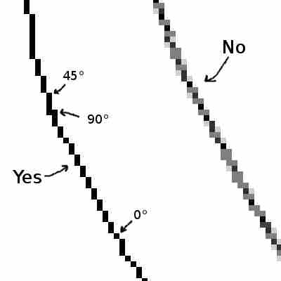
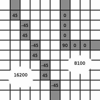
One of the simpler approaches if your line is an actual stroke is an angle squared algorithm. Trace along the pixels of the line. Look at the angle between the previous point, the current point, and the next point. Square the angle, and accumulate it. Squaring it gets rid of the sign for positive/negative angles, and it makes sharper angles far more important.  End the line segment once the accumulated value passes a threshold you figure out experimentally based on your needs. The higher your threshold the more curve can accumulate. If you're worried about overly long segments, you might also include an accumulated line length and end it there.

More advanced methods involve building a curve and fitting it to match. Building splines or Bézier curves that match the picture, or using the least-squares method to fit the curves, they are compute expensive but searches for curve fitting algorithms should find them.

If you don't have the individual strokes, an option is to look for breaklines by running some filters over the image to find curve segments, or for images with less clear boundaries, using gradient descent algorithms to find those segments. They're far more image processing work, but they'll generate strokes for you. Many image processing toolkits have that built in, such as using a Hough Transform to pick out the lines for processing.  Once you have strokes you can use the algorithms above. 

1 hour ago, Outliner said:

Aside from trying to convert an image into a mesh, representing levels as images is a very appealing idea.

It is fairly common.  Most image formats are little more than a fancy 2D array. I've worked on small tile-based games that stored levels as image data, they could encode and compress their levels and metadata using a lossless image format. 

Advertisement
4 hours ago, frob said:

One of the simpler approaches if your line is an actual stroke is an angle squared algorithm.

What exactly does "an actual stroke" mean? What sort of line is not an actual stroke? Based on context, I'm going to guess that a stroke is a 1-pixel-wide series of uniformly colored pixels so that for any pixel on the stroke there is a clear next pixel and previous pixel. In contrast, a non-stroke line would be the sort of line often produced by image editors where it is more than one pixel wide and where the color varies due to antialiasing along the edges of the line. Here's an image illustrating my idea of a stroke versus a non-stroke line:

Stroke1.jpg.7a57b266f4f43ff4e347dafc4f0e69f9.jpg

The curve on the left is a stroke and the curve on the right is not a stroke. Correct? I have also marked angles onto a few of the stroke pixels to illustrate my understanding of the angle squared algorithm.

4 hours ago, frob said:

Look at the angle between the previous point, the current point, and the next point.

I'm guessing this means that a straight line through these points is measured as 0-degrees rather than 180-degrees. That way the angle increases as the bend in the line gets sharper, rather then decreasing.

4 hours ago, frob said:

Square the angle, and accumulate it.

What is the accumulation trying to measure? I notice that fairly straight lines can have high accumulations while sharply bent lines can have much lower accumulations. Here is an illustration:

Stroke3.jpg.57baa99e6dd88901186bf066818f9790.jpg

The line on the left makes 45-degree bends when we measure pixel-by-pixel, but overall it is quite straight. This portion of the line has an accumulation of 16200, and that will just keep getting bigger as the line continues on its current straight path. In contrast, the bent line on the right has one 90-degree corner and all zeroes everywhere else, so its accumulation is 8100 and it will stay that low no matter how long it is.

It feels like it would make more sense if we didn't square the angles, so the positive 45s would cancel the negative 45s.

Another issue is in determining which pixel is the next pixel. For example, suppose we wanted 135-degree turn in the line. When we get to the corner there are apparently two pixels which might be considered the next pixel, as illustrated here:

Stroke2.jpg.5e67e6cc0d1c6a6a29c3be9714812a6a.jpg

A similar issue arises when two lines cross each other. This problem should be easy enough to solve by implementing special cases which look ahead more than one pixel and are particularly programmed to recognize intersections and 135-degree corners, but I wonder if I'm on the right track and correctly understanding what you had in mind.

4 hours ago, frob said:

Building splines or Bézier curves that match the picture, or using the least-squares method to fit the curves, they are compute expensive but searches for curve fitting algorithms should find them.

On the contrary, searching suggests this is quite difficult or impossible. This may not have been mentioned specifically, but unlike the illustration I gave in the first post, an actual level in a game should be expected to have more than one curve. Here is a Stack Overflow question on this very topic: fitting multiple curves to set of points. No useful answers ever appeared. The usual content we get when searching for least-squares fitting is how to fit a function to given data, but we're not really looking for a function. We're looking to fit a set of curves to data, and algorithms to achieve that are much harder to come by.

5 hours ago, frob said:

Many image processing toolkits have that built in, such as using a Hough Transform to pick out the lines for processing.

Hough Transform is a fascinating technique. I suspect that if I have to resort to Hough Transform it means that I'm doing something wrong, but if it's a technique that actually gets used in game development than perhaps I should try it. I would love to find a guide on using Hough Transform or similar processes to find lines in images and then turn those images into game level meshes.

14 minutes ago, Outliner said:

What exactly does "an actual stroke" mean? What sort of line is not an actual stroke?

Dealing with raw pixel data is difficult for exactly the reasons you mention, which is why I described it as strokes and lines.

Raw pixel data you need to determine how many pixels form a line, they can suffer issues from anti-aliasing, from tiny gaps, from line thickness. You won't know how to proceed when lines intersect each other or touch or otherwise converge. You need to break the pixel data into lines so you know where to segment the terrain.

Image processing tools usually have line detection functionality built in. Some call them line detection. In some processing tools they are called breaklines. Other tools call them other names. Usually the tools reduce the lines they detect into small multi-pixel segments.

If you're looking from a stroke drawn with a pen on a touch-based surface, they produce sample points that are also typically more than one point long.  You can use the stroke data if you have it.

It is far better to rely on an existing image processing library for this rather than to implement all the algorithms yourself.  The only good reason to implement them yourself is if you are trying to learn the algorithms or are doing research on modifying the algorithms.

Rather conveniently, ImageMagick can extract those values with the convert tool and the output is an array of stroke lines. You can use the stroke lines directly if you're using the API, or you can have the convert tool dump the stroke lines in Magick Vector Format (MVF). Example of it for various images is here, although the full color images are far more than what you're looking for with a black and white line.

24 minutes ago, Outliner said:

What is the accumulation trying to measure? I notice that fairly straight lines can have high accumulations while sharply bent lines can have much lower accumulations.

That is exactly the case, yes.  

All those problems you describe are issues if you are dealing with pixel points directly.  That's why I wrote in the earlier replies that you need to deal with strokes, not pixels.  Pixels are the wrong tools.  If you can get stroke points directly from the input device (such as a digital pen) it is easiest. It is more difficult if you must convert pixel data into strokes.

When dealing with stroke points rather than pixels, trying to turn stroke points into well-spaced mesh points means placing the mesh points reasonably far apart. If the points are too close you get a high number of triangles.  Usually (but not necessarily always) the most critical points are the ones around a turn.  You can have an extremely long mesh line when the cut is straight. When you have a gentle curve you want more points.  When you have a sharp angle you want the point of the angle.  If you had a threshold of 2500, then any sharp angle of at least 50 degrees would automatically be a mesh point. A gentle curve may take some distance before reaching the threshold, and a near-perfectly straight line could go a long distance before 

Accumulating angles themselves, such as +45 cancelled by a -45, that means that a wavy line that doesn't quite hit the threshold will constantly cancel itself out, and you'll only have mesh points at the beginning and end of the line. That won't generate a curvy mesh line even though the line is wavy. With the sum of the squares, the sum increases rapidly as the curve begins to bend so a mesh point will be added. During the minima and maxima of the wavy line, the straighter segments will be simplified with very few mesh points.  It generates a nice wavy mesh line, and you can adjust how close the mesh line fits the curve by adjusting the threshold after some experimentation.

That is why it is critical to convert the drawing image into strokes or line segments first.  It is the angle of stroke segments, not the angle of pixels, that tell you where to split your mesh.

34 minutes ago, Outliner said:

Here is a Stack Overflow question on this very topic: fitting multiple curves to set of points. No useful answers ever appeared. The usual content we get when searching for least-squares fitting is how to fit a function to given data, but we're not really looking for a function. We're looking to fit a set of curves to data, and algorithms to achieve that are much harder to come by.

That question is asking something considerably different. They are trying to fit an arbitrary number of curves into arbitrary points.  The answer is correct that there are no good minima. The question is asking for an NP-hard solution (what is the absolute best path, the question is equivalent to the traveling salesman problem) but they want to use a type of curve that will always have the same cost no matter how many of the curves they use, with no conditions of starting point.  It doesn't matter if they use one or ten that they were asking for, the answer is always the same.  Said differently, with 18 points they are asking for a 'best' answer that has about 540 trillion solutions where each answer is nearly identical.

This question here is if you can turn a single strip of pixel points into a single parametric curve.  And the answer there is absolutely yes, even if that means a parametric curve fitted pixel by pixel. A least squares algorithm will quickly generate a tight curve, which is why I would recommend it if you're trying to build your stroke data yourself.  As mentioned I'd prefer to use an existing library for it, but  if you're doing it yourself, the least squares curve fitting to generate your curve strokes will give good results quickly.  Then you're not dealing with pixels, you're dealing with points on a parametric curve, and those can be used with the sum-of-the-squares subdivision method described above.

But you probably won't need to do it.  Just use an existing image processing library like ImageMagick and be done.

53 minutes ago, Outliner said:

I suspect that if I have to resort to Hough Transform it means that I'm doing something wrong, but if it's a technique that actually gets used in game development than perhaps I should try it.

It gets used all the time in image processing for extracting line segments from images.  There is no reason to implement it yourself, just download ImageMagick and use the existing function.  Or if you have another image processing library you prefer, use that and find their edge extraction tools.


All this writing about extracting line stroke information from the image.  

Getting back to the big task, use your image processing library to generate the line segments for you, or if you want a challenge do it yourself to learn the math. Create a regular grid as your starting mesh. Step along the lines and use one of the various triangle segmentation algorithms mentioned above, which will start to turn your mesh into polygon soup. Record the points as you traverse the segments. Add height, add walls, turning your mesh into a difficult-to-understand collection of vertices and indeces. Feed the polygon soup into a D3D mesh as a vertex buffer and index buffer. Let D3D optimize the mesh for you. That finishes the visual mesh.

1 hour ago, frob said:

Pixels are the wrong tools.  If you can get stroke points directly from the input device (such as a digital pen) it is easiest. It is more difficult if you must convert pixel data into strokes.

This is why I was surprised to see so many suggestions related to raster images. Rasters are nothing but pixels. They are delightfully easy to make, but they never seemed like they would be enough. Naturally we'll make any level editing tools that the game requires, so we'll have stroke points if we want stroke points.

The reason I allowed myself to consider the possibility of using raster-based solutions was because rasters are so much easier to edit. A stroke is easy to create initially by a simple gesture of a pen or mouse, but it gets fiddly if you want to modify it later, like extending it or erasing and replacing part of it. Now that it's clear that the simple raster is not enough, I will need to research user interface solutions to easy stroke editing.

On the other hand, the simplest user interface would be to just let the user edit a raster and find a good library to extract stroke information from the raster. I'm afraid that the library would end up misinterpreting what the user was trying to draw, and the user would end up fighting with the library.

2 hours ago, frob said:

It gets used all the time in image processing for extracting line segments from images.

No doubt that's true, but I'd be surprised if that sort of image processing is often used in game development.

2 hours ago, frob said:

Step along the lines and use one of the various triangle segmentation algorithms mentioned above, which will start to turn your mesh into polygon soup.

It is remarkably hard to find good information about those algorithms on the web. Even so, I think I'm starting to understand. I was confused because I kept focusing on the grid of squares and trying to triangulate each square based on the segments passing through it with complicated techniques like ear clipping.

Now that I ignore the squares and look at each grid cell as being fundamentally a pair of triangles, the problem becomes triangulating a triangle when a segment passes through it, and we only ever need to worry about one segment passing through a triangle, because after the first segment passes through a triangle the triangle gets broken down into smaller triangles. Any future segments will pass through those smaller triangles.

When it is just one triangle and one segment, there are really only 3 very simple cases to consider:

ABC.gif.f2400865dbcc8298b1b4fbb322f76a06.gif

  • A: One endpoint of the segment is inside the triangle. The triangle becomes 4 triangles centered around the endpoint (green) with the segment (blue) running between two of the triangles. Two new vertices are added: the endpoint and a vertex in the edge of the original triangle. Perhaps this is the triangle fan you were talking about and I just didn't understand until now.
  • B: Both endpoints of the segment are in the triangle. We triangulate around the first endpoint (green) to split the existing triangle into 3 new triangles, then we determine which new triangle contains the second endpoint (red) and split that triangle around that endpoint. We just need a new vertex for each endpoint and a total of 5 new triangles.
  • C: The segment passes through the triangle completely. We split the two edges that the segment passes through, turning the triangle into a smaller triangle and a quad, then split the quad into two triangles.

We also need to consider edge cases where segments or endpoints land exactly on existing edges or vertices, but at that point we're just mopping up the details. The above three cases represent the bulk of the problem of splitting an existing mesh along arbitrary curves, and now it seems so easy.

7 hours ago, Outliner said:

and now it seems so easy.

Good to know.

XP+ for you. 

This topic is closed to new replies.

Advertisement