Diffuse Reflection - Ray- / Pathtracing

Started by
13 comments, last by IsItSharp 6 years ago

For my simple pathtracer written in C I need a function which calculates a random, diffuse reflection vector (for diffuse / lambert material). 

This is my function header:


struct Ray diffuse(const struct Sphere s, const struct Point hitPoint)

where s is the intersected Sphere and hitPoint is the point a ray intersected the sphere.

Of course there are several projectes and their source code available on GitHub but most of the time they are doing way more things than I can understand at once.

I don't want to just copy their code (I want to understand it myself) and I did not get any usefull results from google.

I don't know where to start.

Advertisement

the most trivial way I'd come up with.


vec3 diffuse(float u,float v)
{
	float radius = 1.f-sqrt(v);
    u = u * 2.f * FLT_PI;
    return vec3(cosf(u)*radius,cosf(u)*radius,v);
}


You can google information about it using "uniform hemisphere sampling" or in particular for diffuse "cosine hemisphere sampling"


Thanks for your reply!

I don't think that approach checks if the point is actually outside the intersected sphere?

What's about u and v? Wikipedia told me they are calculated like this:


    double u = p.x / length(p);
    double v = p.y / length(p);

But what is the intersected Sphere used for?

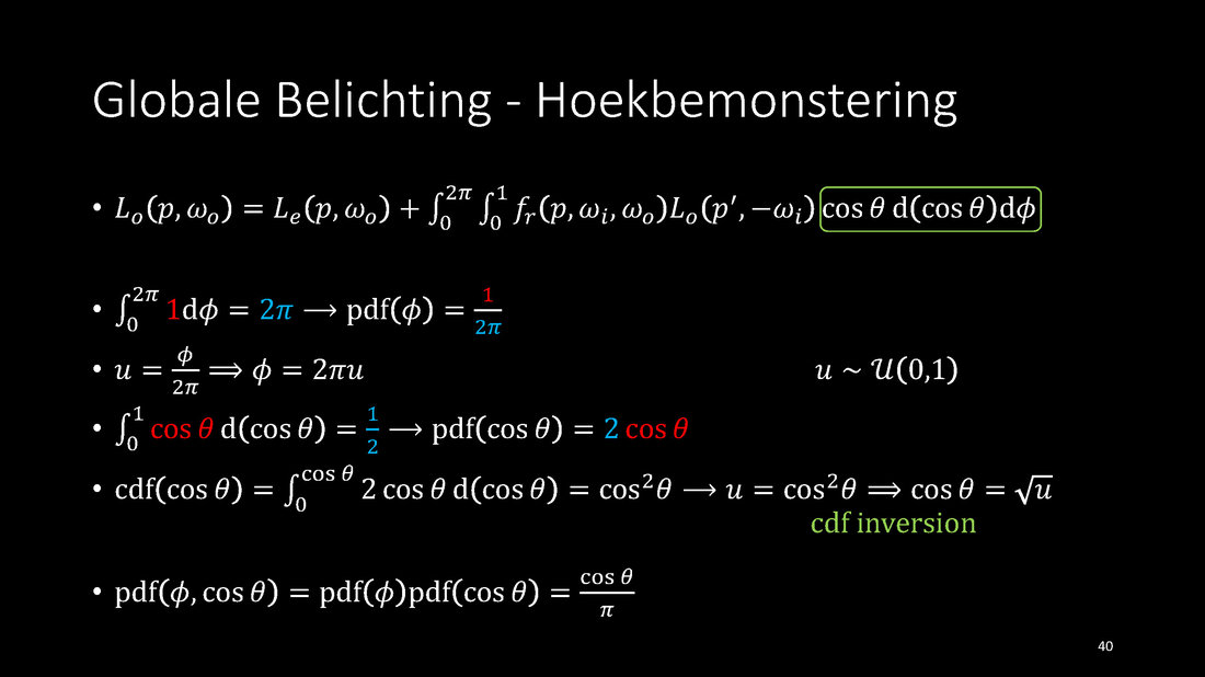
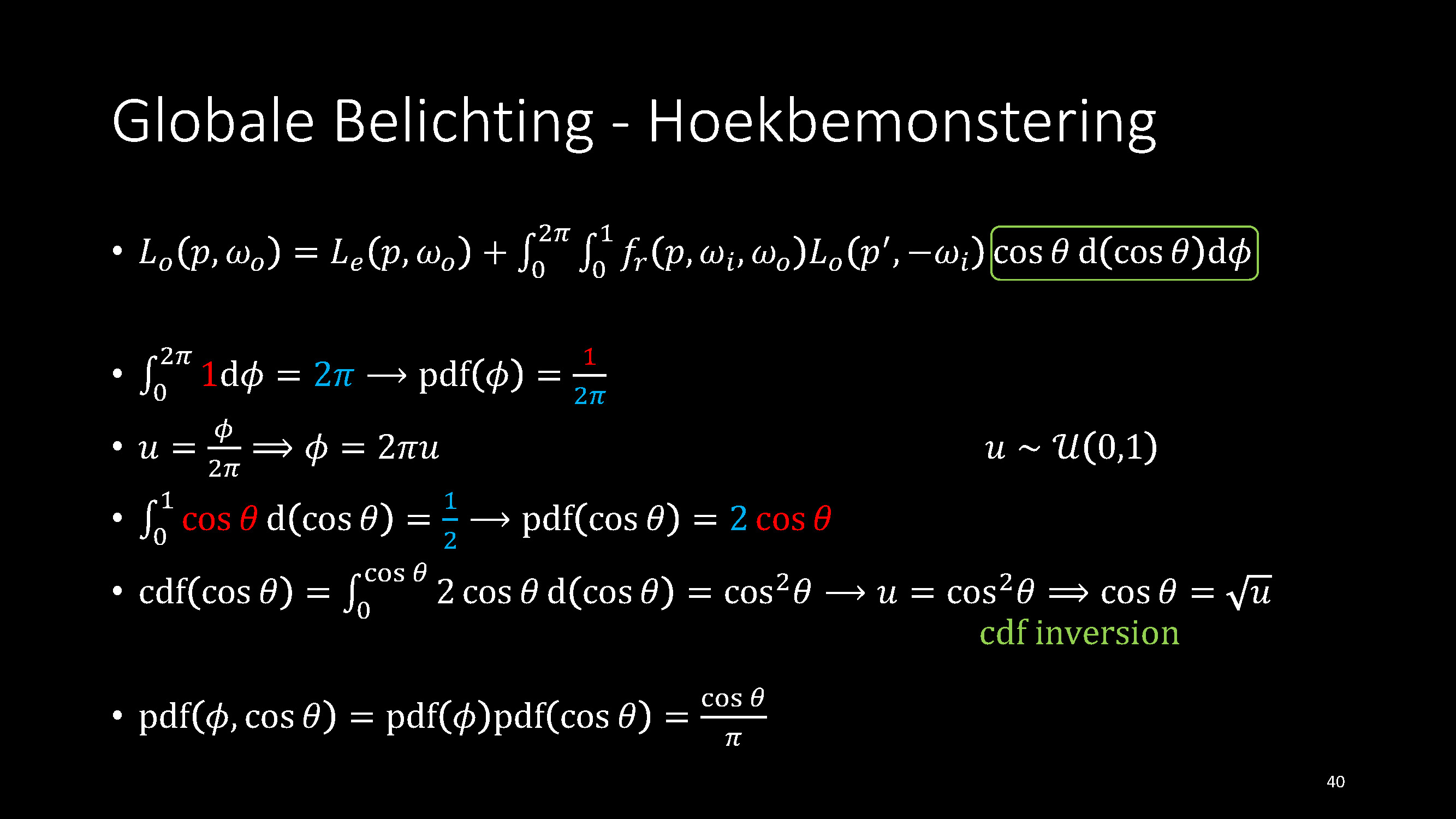
Brute-force path tracing using Cosine-Weighted Hemisphere Sampling applied to the Rendering Equation:

5abf9200a4a10_ComputergrafiekProjectDeel3.thumb.jpg.6c9697d03a279dd04cd1320d9c0ce9c9.jpg

(P.S.: the title is in Dutch, since I need to teach this in a Dutch course, but is not really required to understand the big picture)


Once, you have sampled a vector over a standard hemisphere (e.g. hemisphere spanned about the z axis) using Cosine-Weighted Hemisphere Sampling, you need to construct an orthonormal base around the actual shading normal to transform your sampled vector from a standard hemisphere to the hemisphere spanned about the shading normal.

By including the cosine factor in the sampling strategy, you can completely eliminate noise caused by this factor. It is a common practice to include both the BRDF and cosine factor in the sampling strategy to reduce all noise caused by these factors, but that is a no-op for a Lambertian BRDF. Since, the cosine is part of the pdf, it cancels the cosine of the integrand. (You can even "cancel" the pi of your Lambertian BRDF. ;) )


To construct the orthonormal base starting with just one basis vector (i.e. shading normal), you can use one of the methods in this repository.


To combine all of this in a path tracer, you can even take a look at this repository, pick a language you like, and you can easily find the few statements related to these topics.

🧙

1 hour ago, IsItSharp said:

Thanks for your reply!

I don't think that approach checks if the point is actually outside the intersected sphere?

What's about u and v? Wikipedia told me they are calculated like this:


    double u = p.x / length(p);
    double v = p.y / length(p);

But what is the intersected Sphere used for?

it generates a vector on the sphere, not inside, not outside, but exactly on a unit sphere.

u and v are two input seeds that you have to provide, to get the corresponding output vector. This values depend on your sampling approach, could be two fully random vectors, or maybe based on stratified sampling, could be a regular grid, some sequence (e.g. halton) or however you want to approach it.

Thanks for your answers!

Does anyone have an idea about what is going wrong here? It's kinda hard do debug a pathtracer (for me at least):

https://picload.org/view/dapdacrr/test.png.html

My trace-function:


struct RGB trace(const struct Ray ry, int tdepth) {
    if(tdepth == TRACEDEPTH) return (struct RGB){.r = 0, .g = 0, .b = 0};

    double hitDistance  = 1e20f;
    struct Sphere hitObject = {};
    for(int i = 0; i < (sizeof(spheres) / sizeof(spheres[0])); i++) {
        double dist = intersectSphere(spheres[i], ry);
        if(dist > -1.0 && dist < hitDistance) {
            hitDistance = dist;
            hitObject = spheres[i];
        }
    }

    if(hitDistance == 1e20f) return (struct RGB){.r = 0, .g = 0, .b = 0};
    if(hitObject.isEmitter) return hitObject.color;

    const struct Point hitPoint = add(ry.origin, mult(ry.dir, hitDistance * 0.998));
    const struct Point nrml = sphereNormal(hitObject, hitPoint);
    struct Point rnd = diffuse();

    /* Wrong hemisphere */
    if(dot(rnd, nrml) < 0.0)
        rnd = mult(rnd, -1.0);

    const struct Ray reflectionRay = (struct Ray){ .origin = hitPoint, .dir = norm(rnd) };

    struct RGB returnColor = trace(reflectionRay, tdepth + 1);
    int r = hitObject.color.r * returnColor.r;
    int g = hitObject.color.g * returnColor.g;
    int b = hitObject.color.b * returnColor.b;

    r /= 255.0;
    g /= 255.0;
    b /= 255.0;

    return (struct RGB){ .r = r, .g = g, .b = b};
}


It usually helps to split a big problem into smaller stages and get every step working individually.

From the image, it looks as if something with the first hit is wrong, aka camera rays, as there is some interlacing. (I would guess your "SetPixel" might be somehow wrong.) For debugging, you could try to just visualize the first hit and output the pure diffuse color. If that works, add some explicit tracing to a light source (e.g. point light), with old school lighting calculations.

This is my generateCameraRay() - function:


    const double fov = 105.0 * M_PI / 180.0;
    const double zdir = 1.0 / tan(fov);

    double aspect = (double)h / (double)w;

    double xH = x + (halton(2, samples)) - 0.5;
    double yH = y + (halton(3, samples)) - 0.5;

    double xdir = (xH / (double)w) * 2.0 - 1.0;
    double ydir = ((yH/ (double)h) * 2.0 - 1.0) * aspect;

    const struct Point dir = norm((struct Point){.x = xdir, .y = ydir, .z = zdir});
    return (struct Ray){.origin = c.pos, .dir = dir};


I checked only the first hit and even this has this interlacing effect.

make a 32x32 image and step with your debugger pixel by pixel, check why every 2nd line is black (or not written). (From a glance on it, your ray generation code looks fine. Maybe avoid doing halton for now, just to keep the count of possible error sources low.

Okay, I now noticed that this interlacing problems appears if WIDTH != HEIGHT

This topic is closed to new replies.

Advertisement