Me again.
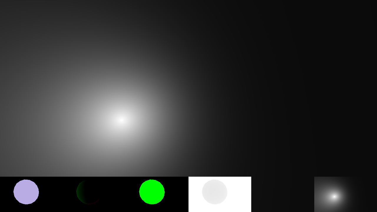
I noticed a weird issue with color banding in my current PBR shader. After a bit of experimentation i noticed that the fresnel calculation seems to be the culprit.
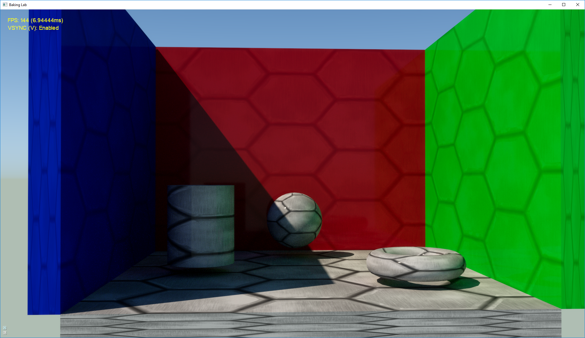
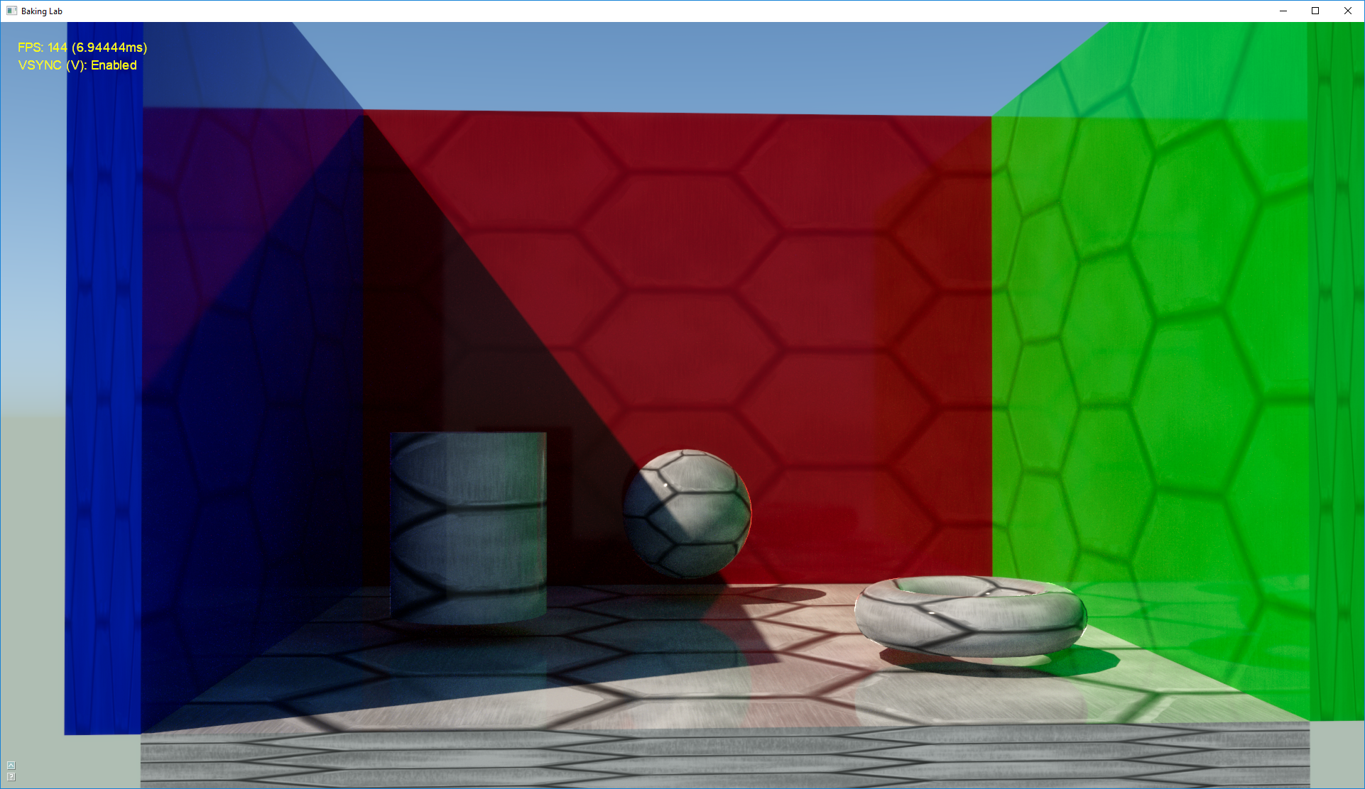
Here is how the colorbanding looks like (it's a bit dark, but noticeable):
I also think that the fresnel calculation is a bit off.
This is the actual shader (stripped everything away except the fresnel calculation:)
vec3 BRDF_F_FresnelSchlick(float VdotH, vec3 F0)
{
    return (F0 + (1.0f - F0) * (pow(1.0f - max(VdotH,0.0f),5.0f)));
}


void main()
{

	vec2 texCoord = vec2(gl_FragCoord.x * uPixelSize.x,gl_FragCoord.y*uPixelSize.y);

	vec3 fragPos = depthToWorld(gDepth,texCoord,uInverseViewProjectionBiased);
	vec3 fragNormal = texture2D(gNormal, texCoord).rgb;


	//--------------
	vec3 fragToLightNormal = uLightPos-fragPos;


	vec3 N = normalize(fragNormal);//normal vector
	vec3 L = normalize(fragToLightNormal);//light vector
	vec3 V = normalize(uCameraPosition-fragPos.xyz); //eye vector
	vec3 H = normalize(L+V); //half vector

	float NdotH = max(dot(N,H),0.0f);
	float NdotV = max(dot(N,V),0.0f);
	float NdotL = max(dot(N,L),0.0f);
	float VdotH = max(dot(V,H),0.0f);


	vec3 F0 = vec3(0.04f,0.04f,0.04f);//assumption

	vec3 color = BRDF_F_FresnelSchlick(VdotH, F0);

    outputF = vec4(color,1.0f);


}
It's worth noting that i'm writing those values into a 16 bit floating point buffer. (So the FBO precision shouldn't be the culprit.)
Is this a math based precision error? (especially in the pow() function)
Also another thing i noticed,
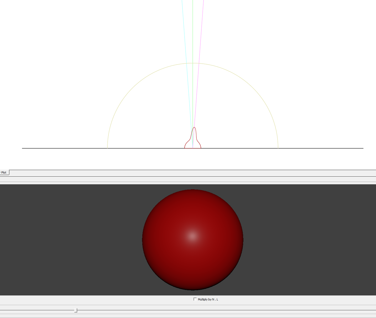
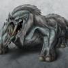
The fresnel effect is supposed to look like this: (picture shamelessly stolen from google)

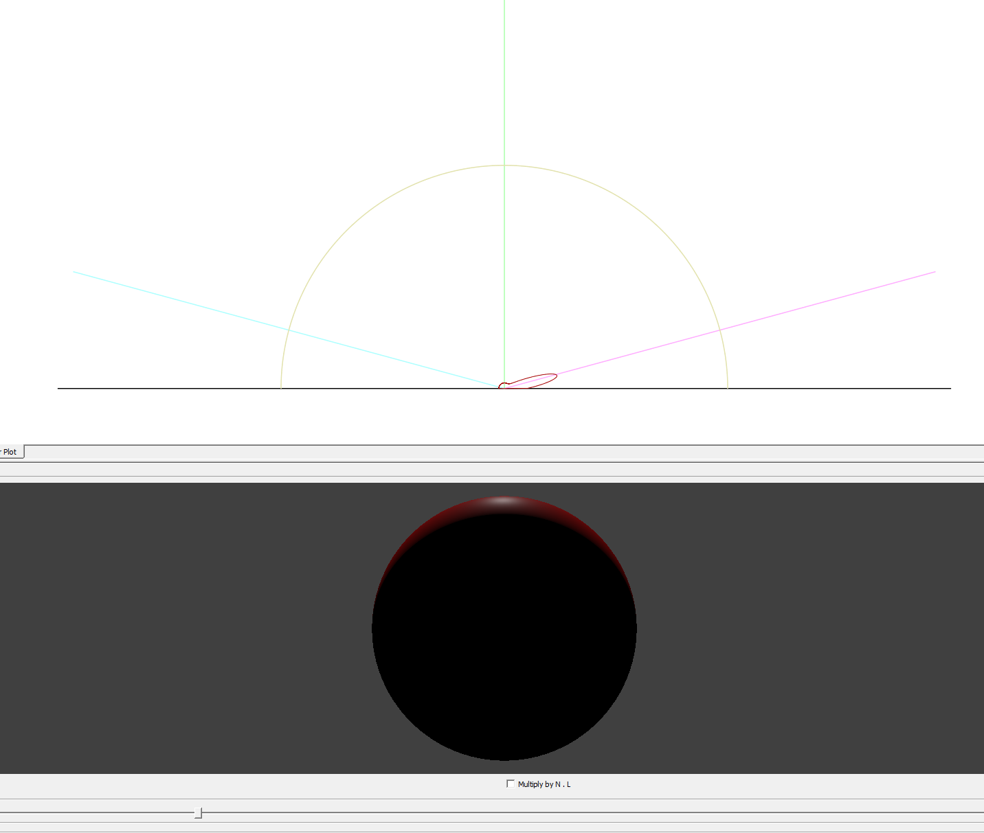
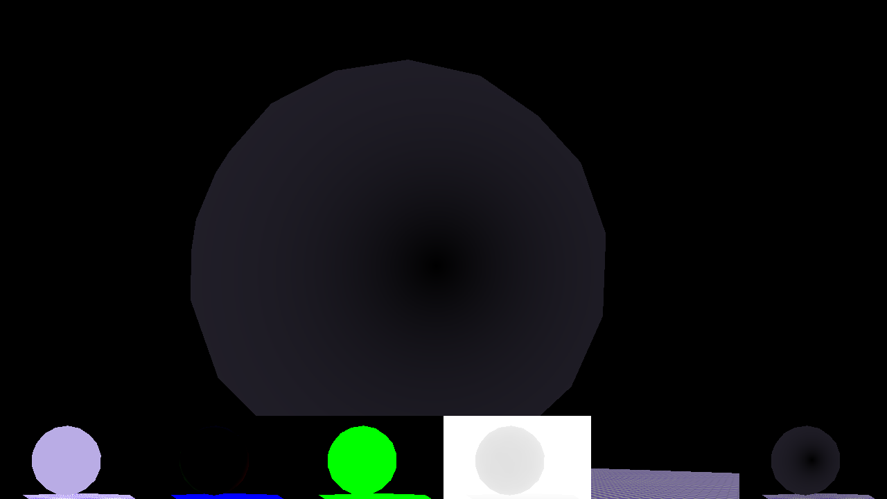
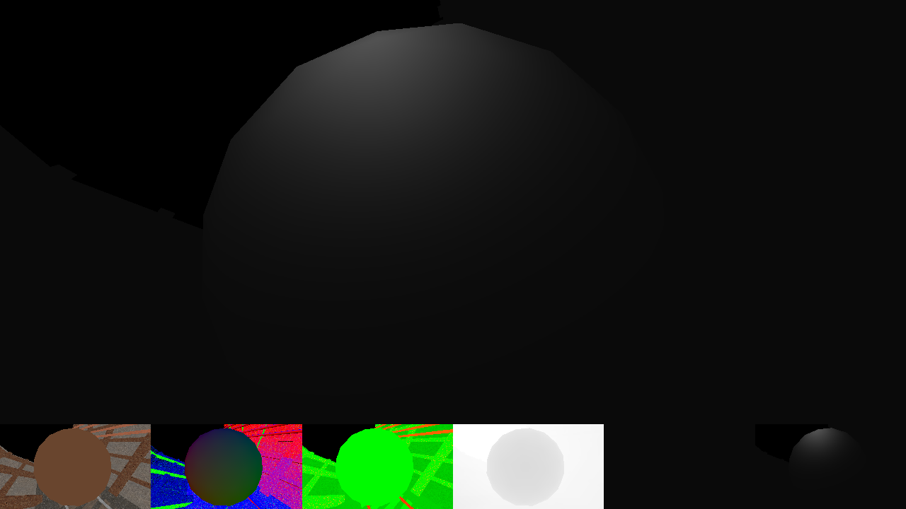
However, no matter what i do i never get this effect in my shader. (I tried all lighting conditions and material values.) Here is what a material with 50% roughness and 50% metallic value looks like:
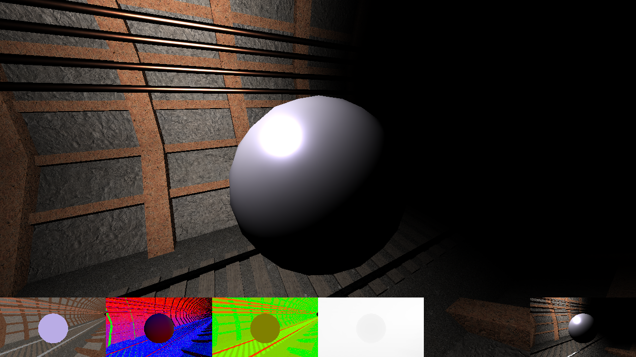
Front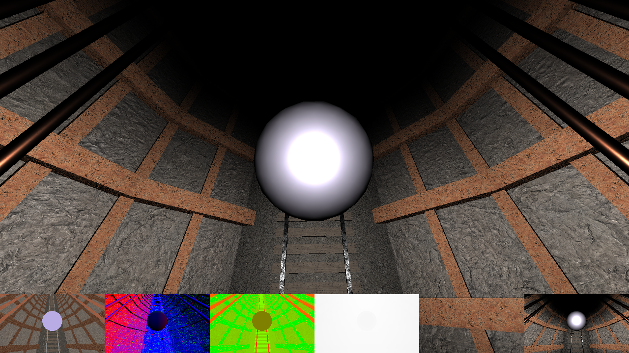
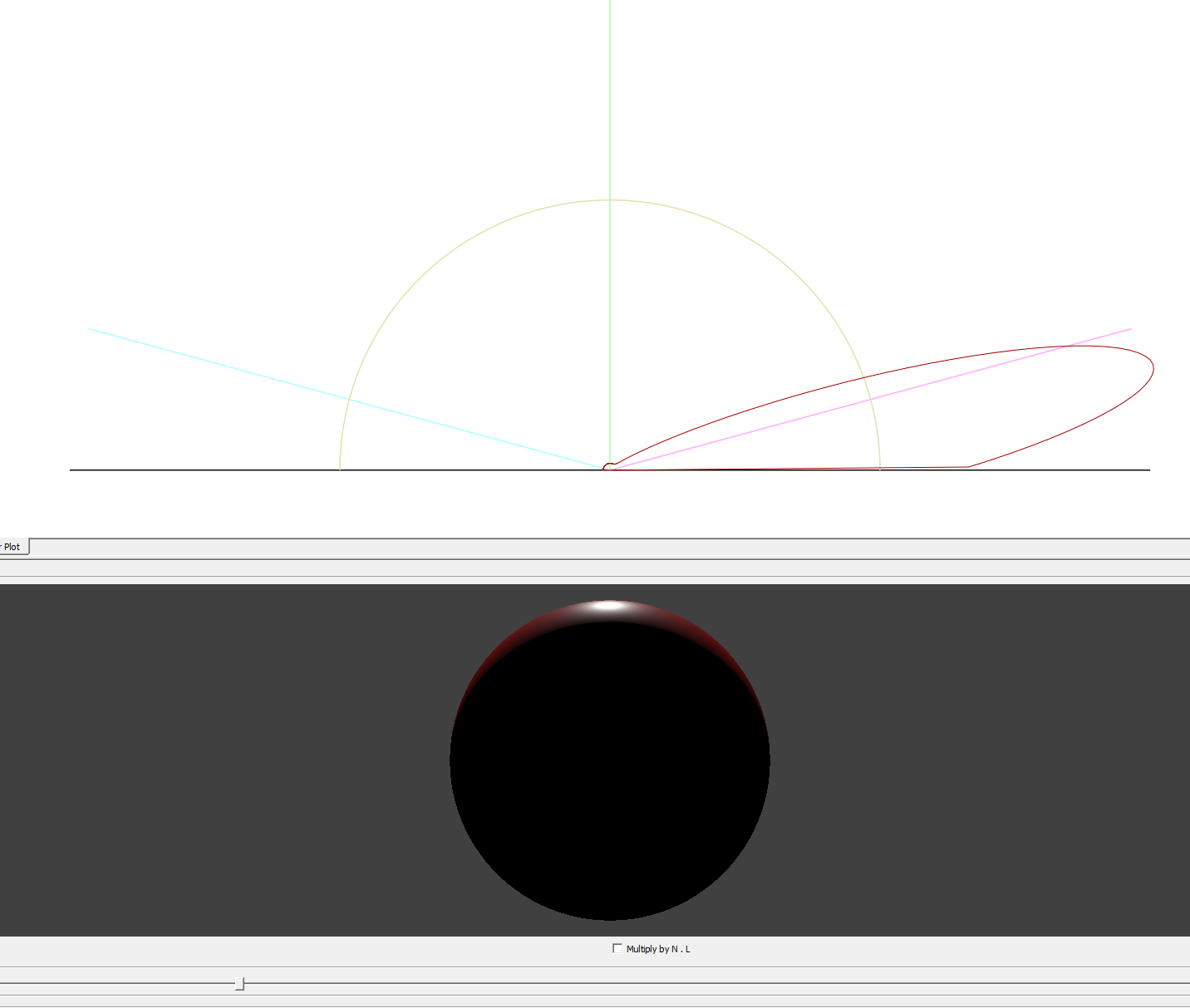
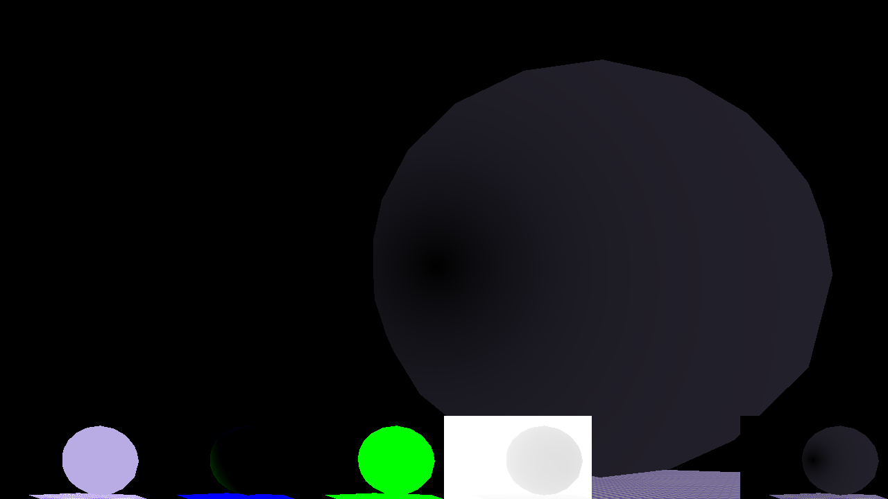
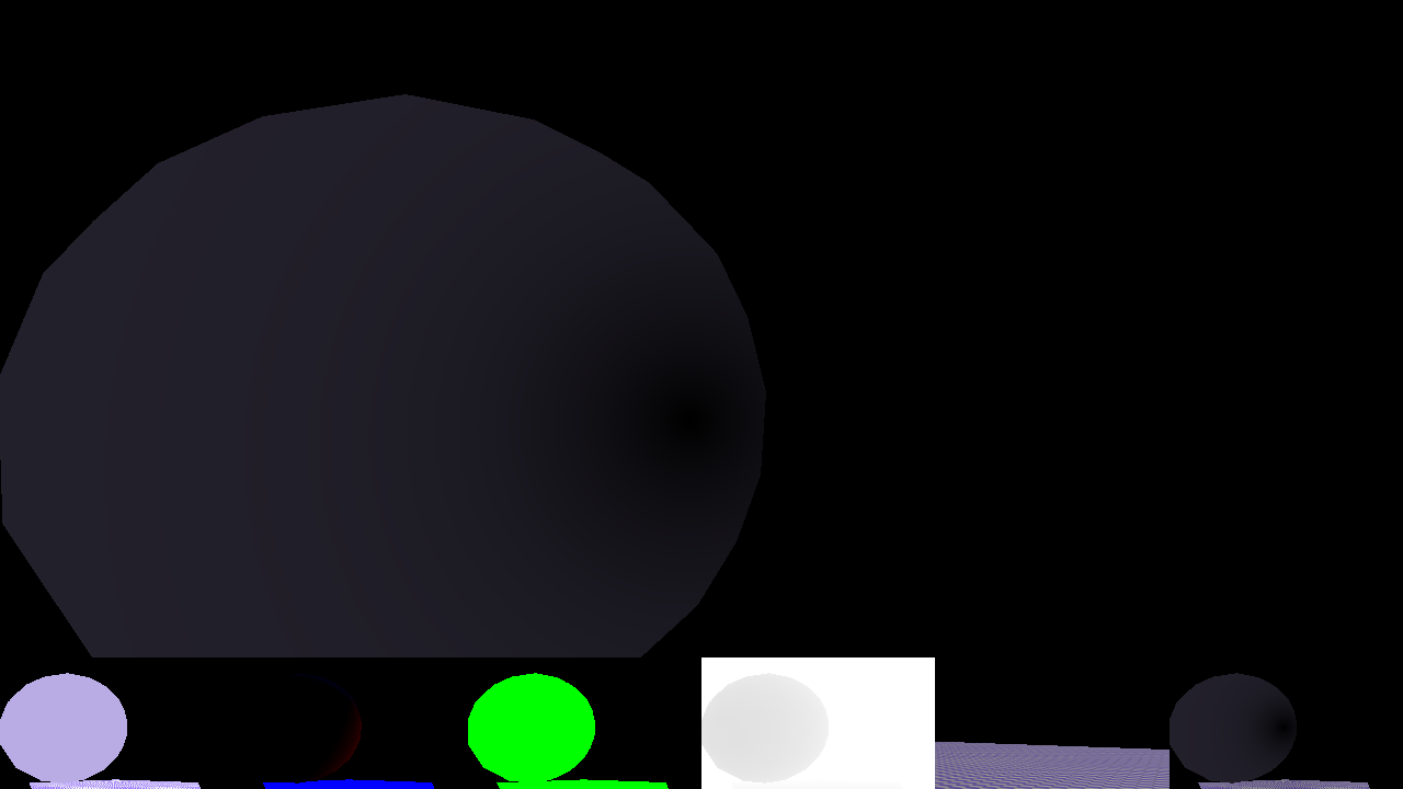
From behind: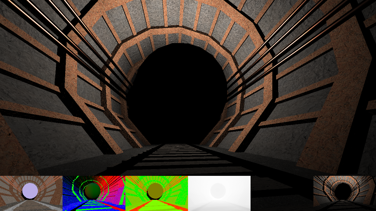
I noticed that switching the "VdotH" dot product to "LdotV" makes this effect somewhat work, but i read conflicting information on the internet as if this is even correct.
Here is the complete shader:
#version 330


in vec2 vTexcoord;
out vec4 outputF;

uniform sampler2D gDepth;
uniform sampler2D gNormal;
uniform sampler2D gAlbedo;
uniform sampler2D gMetallicRoughness;


uniform vec2 uPixelSize;
uniform float uLightRadius;
uniform vec3 uLightColor;
uniform vec3 uLightPos;
uniform vec3 uCameraPosition;


const float PI = 3.141592653589793;


uniform mat4 uInverseViewProjectionBiased;


vec3 depthToWorld(sampler2D depthMap,vec2 texcoord,mat4 biasedInverseProjView){
		float depth = texture2D(depthMap,texcoord).r;

        vec4 position = vec4(texcoord,depth,1.0);

        position = ((biasedInverseProjView)*position);
        return vec3(position/position.w);
}


float BRDF_D_GGX(float NdotH, float roughness)
{
	float roughness2 = roughness * roughness;
	float roughness4 = roughness2 * roughness2;

	float denomA = (NdotH*NdotH * (roughness4 -1.0f) + 1.0f);
	return roughness4 / (PI * denomA * denomA);
}

//NdotV seems to be correct (instead of HdotV)
vec3 BRDF_F_FresnelSchlick(float VdotH, vec3 F0)
{
    return (F0 + (1.0f - F0) * (pow(1.0f - max(VdotH,0.0f),5.0f)));
}


float BRDF_G_SchlickGGX(float NdotV,float roughness){
	float k = (roughness*roughness)/2.0f;
	return (NdotV)/(NdotV * (1.0f - k) + k);
}

//geometrix shadowing - cook-Torrance
float BRDF_G_Smith(float NdotV,float NdotL, float roughness)
{
	NdotV = max(NdotV,0.0f);
	NdotL = max(NdotL,0.0f);

	return BRDF_G_SchlickGGX(NdotV,roughness) * BRDF_G_SchlickGGX(NdotL,roughness);

}

float calcAttenuation(float distToFragment,float lightRadius){
	float att = clamp(1.0 - distToFragment*distToFragment/(lightRadius*lightRadius), 0.0, 1.0);
	att *= att;

	return att;
}


void main()
{

	vec2 texCoord = vec2(gl_FragCoord.x * uPixelSize.x,gl_FragCoord.y*uPixelSize.y);

	vec3 fragPos = depthToWorld(gDepth,texCoord,uInverseViewProjectionBiased);
	vec3 fragNormal = texture2D(gNormal, texCoord).rgb;
	vec3 fragAlbedo = texture2D(gAlbedo, texCoord).rgb;
	vec2 fragMetallicRoughness = texture2D(gMetallicRoughness, texCoord).rg;
	float fragMetallic = fragMetallicRoughness.r;
	float fragRoughness = fragMetallicRoughness.g;

	fragRoughness = max(fragRoughness,0.05f);//if value is 0 it doesnt reflect anything


	//--------------
	vec3 fragToLightNormal = uLightPos-fragPos;


	vec3 N = normalize(fragNormal);//normal vector
	vec3 L = normalize(fragToLightNormal);//light vector
	vec3 V = normalize(uCameraPosition-fragPos.xyz); //eye vector
	vec3 H = normalize(L+V); //half vector

	float NdotH = max(dot(N,H),0.0f);
	float NdotV = max(dot(N,V),0.0f);
	float NdotL = max(dot(N,L),0.0f);
	float VdotH = max(dot(V,H),0.0f);

	//------------------

	vec3 F0 = vec3(0.04f,0.04f,0.04f);//assumption
	F0 = mix(F0,fragAlbedo,fragMetallic);


	float D = BRDF_D_GGX(NdotH, fragRoughness); //normal distribution
    float G = BRDF_G_Smith(NdotV,NdotL,fragRoughness); //geometric shadowing
	vec3 F = BRDF_F_FresnelSchlick(VdotH, F0); // Fresnel

    vec3 specular = (D * F * G) / 4.0f * max(max(NdotL,0.0) * max(NdotV,0.0),0.001);

	//------light----------
	float lightNormalLength = length(fragToLightNormal);
	float attenuation = calcAttenuation(lightNormalLength, uLightRadius);
    vec3 radiance = attenuation * uLightColor;
	//-----------

	vec3 kS = F;
	vec3 kD = vec3(1.0f) - kS;
	kD *= 1.0f - fragMetallic;

	vec3 diffuse = fragAlbedo * kD / PI;
	vec3 color = (diffuse + specular ) * radiance * NdotL;


	//tone mapping (does nothing ATM.)
	float maxExposure = 1.0f;
	color*=1.0f/maxExposure;

    outputF = vec4(color,1.0f);


}
Anyone has an idea why the banding effect takes place and if the fresnel calculation is even correct?