Can I limit my height map noise so it doesn't reach the beginning or end of the texture (in both X and Y axis)?

Started by
6 comments, last by Hashbrown 5 years, 8 months ago

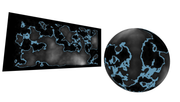
I'm trying to use Perlin Noise to paint landscapes on a sphere. So far I've been able to make this:

Screen_Shot_2018-07-27_at_4.31.23_PM.png
(the quad is just to get a more flat vision of the height map)

I'm not influencing the mesh vertices height yet, but I am creating the noise map from the CPU and passing it to the GPU as a texture, which is what you see above.

I've got 2 issues though:

Issue #1

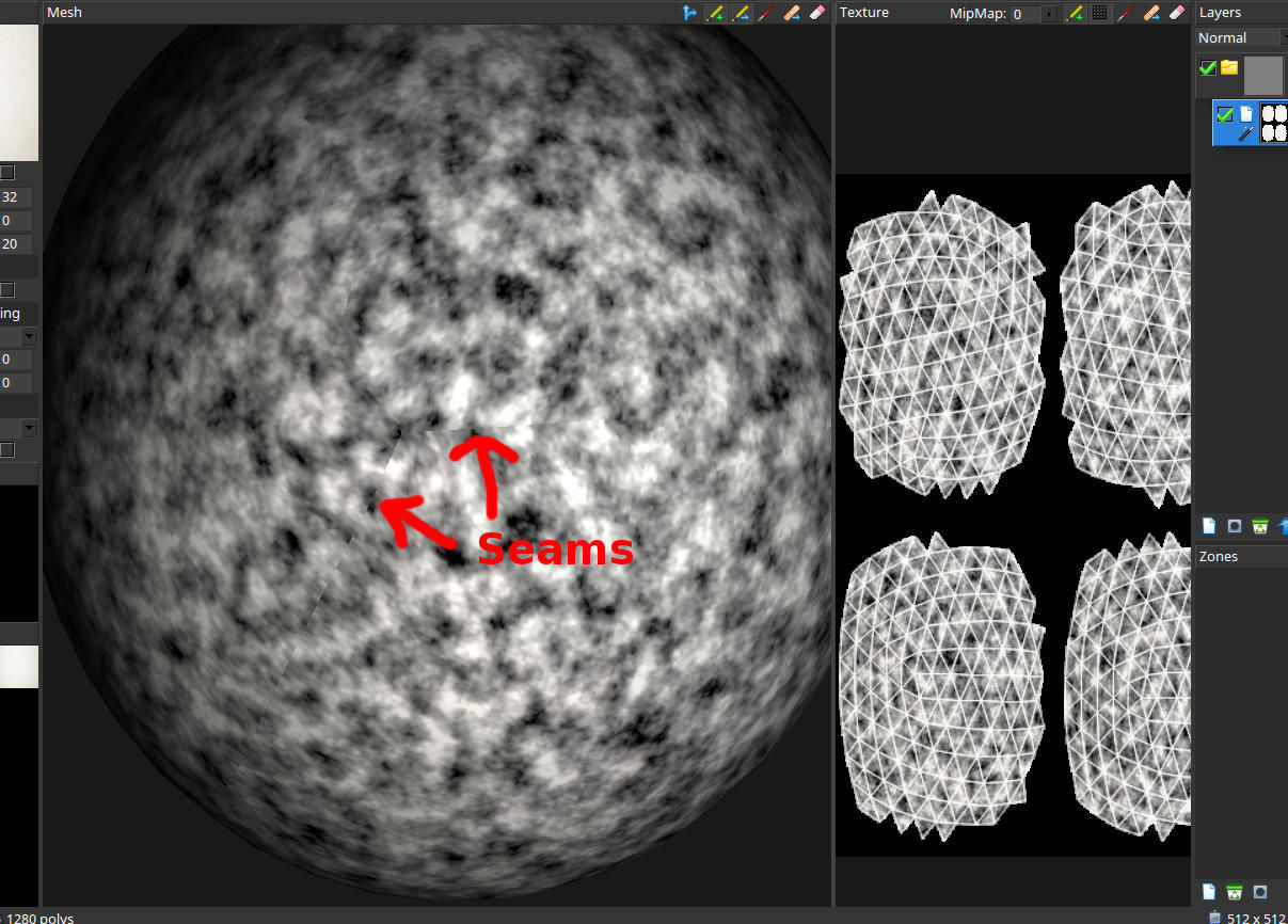
If I get a bit close to the sphere, the detail in the landscapes look bad. I'm aware that I can't get too close, but I also feel that I should be able to get better quality at the distance I show above. The detail in the texture looks blurry and stretched...it just looks bad. I'm not sure what I can do to improve it.

Issue #2

I believe I know why the second issue occurs, but don't know how to solve it. If I rotate the sphere, you'll notice something. Click on the image for a better look: 
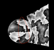
Screen_Shot_2018-07-27_at_4.56.28_PM.png
(notice the seam?)

What I think is going on is that some land/noise reaches the end of the uv/texture and since the sphere texture is pretty much like if you wrap paper around the sphere, the beginning and end of the texture map connect, and both sides have different patterns. 

Solutions I have in mind for Issue #2:

A) Maybe limiting the noise within a certain bounding box, make sure "land" isn't generated around the borders or poles of the texture. Think Islands. I just have no idea how to do that.
B) Finding a way to make the the noise draw at the beginning of the uv/texture once it reaches the end of it. That way the beginning and ends connect seamlessly, but again, I have no idea how to do that. 

I'm kind of rooting for the solution a though. I would be able to make islands that way. Hope I was able to explain myself. If anybody needs anymore information, let me know. I'll share the function in charge of making this noise below. The shader isn't doing anything special but drawing the texture. Thanks! 


CPU Noise Texture:


const width = 100;
const depth = 100;
const scale = 30.6;
const pixels = new Uint8Array(4 * width * depth);

let i = 0;

for (let z = 0; z < depth; z += 1) {
    for (let x = 0; x < width; x += 1) {

        const octaves       = 8;
        const persistance   = 0.5;
        const lacunarity    = 2.0;

        let frequency   = 1.0;
        let amplitude   = 1.0;
        let noiseHeight = 0.0;
    
        for (let i = 0; i < octaves; i += 1) {

            const sampleX = x / scale * frequency;
            const sampleZ = z / scale * frequency;
            
            let n = perlin2(sampleX, sampleZ);
            noiseHeight += n  * amplitude;

            amplitude *= persistance;
            frequency *= lacunarity;
        }

        pixels[i]     = noiseHeight * 255; 
        pixels[i+1]   = noiseHeight * 255;
        pixels[i+2]   = noiseHeight * 255;
        pixels[i+3]   = 255;
    
        i += 4;
    }
}


GPU GLSL:


void main () {
    vec3 diffusemap = texture(texture0, uvcoords).rgb;
    color = vec4(diffusemap, 1.0);
}


Advertisement

I use 3D simplex nose for planets. It's very similar. At first I tried to use 2D noise but I found it wasn't really so suitable for a lot of 3D objects. I had to do some fancy stitching and so forth and even then it had some odd effects.  You might try to simply use 3D noise. It works very well for planets and if you use simplex noise instead of Perlin, you are still only using 4 vectors per value although there is some overhead with skewing and stuff.  I found it was well worth it though.  If you really want to use Perlin nose you can use it in 3D also however.

Edit: I forgot to mention .... If you simply want to fix your seam you can do something similar to what I did when I was messing around with 2d noise (what I called stitching above) .  First you need to make sure your bitmap size is a multiple of your noise gird.  It has to be so for all frequencies, but if you start out like that, and then are dividing by 2 each time, baring rounding errors you should be OK.  Then you have to roll your X noise grid coordinators around using a mod function within the perlin noise function itself, such that the last grid column is a copy of the first.  If you have the source to your noise function it's pretty simple. The problem you will still have is your poles will be compressed, so again 3D is still better.

15 hours ago, Gnollrunner said:

I use 3D simplex nose for planets. It's very similar. At first I tried to use 2D noise but I found it wasn't really so suitable for a lot of 3D objects. I had to do some fancy stitching and so forth and even then it had some odd effects.  You might try to simply use 3D noise. It works very well for planets and if you use simplex noise instead of Perlin, you are still only using 4 vectors per value although there is some overhead with skewing and stuff.  I found it was well worth it though.  If you really want to use Perlin nose you can use it in 3D also however.

Edit: I forgot to mention .... If you simply want to fix your seam you can do something similar to what I did when I was messing around with 2d noise (what I called stitching above) .  First you need to make sure your bitmap size is a multiple of your noise gird.  It has to be so for all frequencies, but if you start out like that, and then are dividing by 2 each time, baring rounding errors you should be OK.  Then you have to roll your X noise grid coordinators around using a mod function within the perlin noise function itself, such that the last grid column is a copy of the first.  If you have the source to your noise function it's pretty simple. The problem you will still have is your poles will be compressed, so again 3D is still better.


Gnoll thanks for answering! I'm definitely going to try Simplex, I found an implementation here. Isn't Simplex under a strict patent though? 

I appreciate answering the seam question too, I'll definitely give it a try that was really annoying me.

As for cutting off certain areas of the noise, I found the answer in this video. The person who made the tutorial calls it a "falloff map". The tutorial is short too, 11 mins long.

Screen_Shot_2018-07-28_at_4.13.04_PM.png
(could use some improvement, but I'm getting there)

I also found out why my texture looked stretched: I was actually stretching the texture! I'm dynamically creating the texture but was making it 512x512, but spheres apparently like images that are wide. So I went with 1000x500 and it looks  so much nicer.

Your issue #2 could be solved in a couple of ways:

1) Make an image that is seamlessly tiling in X using a 2D mapping technique. Note that a 2D mapping doesn't really fit well onto a sphere, without distorting.

2) Make an image from a spherical unwrap. You have some noise function, f, that takes as input a 3D coordinate (x,y,z) and an image that is sized WxH. You can iterate the image on X and Y, calculate normalized coordinates as X/W and Y/H, then apply a transformation of spherical coordinates to Cartesian coordinates as:


for(x=0; x<W; ++x)
{
  for(y=0; y<H; ++y)
  {
    float s=(float)x / (float)W;
    float t=(float)y / (float)H;
    
    // Spherical coords to Cartesian coords.
    float nx=cos(s*2*pi)*sin(t*pi);
    float ny=sin(s*2*pi)*sin(t*pi);
    float nz=cos(t*pi);
    
    PixelValue p = f(nx,ny,nz);
    image.SetPixel(x,y,p);
  }
}

The result of a transform like this gives you an image like:

b8dhHBF.png

which when applied onto the surface of a sphere looks like:

XVMWsM5.png

Since the image was generated from a spherical coordinate, there is no stretching at the equator or compression at the poles. (You can see that in the 2D mapping, it looks stretched along the top and bottom of the image; this is where the mapping approaches the poles of the sphere.) This depends on having your noise function defined as a 3D function, which is simple enough with Perlin noise. And there are no seams, because the spherical->Cartesian mapping ensures that the noise "wraps around" smoothly.

3) Skip the 3D function -> 2D image map -> 3D sphere technique altogether, and just generate the image directly from fragment coords in the shader itself (assuming that is where it eventually ends up). Of course, if you are using the image to distort a sphere like a heightmap, then this doesn't work.

6 hours ago, Hashbrown said:


As for cutting off certain areas of the noise, I found the answer in this video. The person who made the tutorial calls it a "falloff map". The tutorial is short too, 11 mins long.

Actually if you are going to use this, I wouldn't use it for east/west. Just use it for the poles. The reason is, it is really super easy to put in a few lines of code in Perlin noise that will fix the seam problem. This is really not necessary for that. Using it at the poles is just needed to avoid too much stretching of land masses which is harder to fix going from 2D to 3D.    In any case If you fix this with a falloff map you are just limiting what can be generated, and when you generate a lot of worlds it may become obvious that they all have this band of water down one side and no land mass at the polls. Even the earth has Antarctica. The other problem is if you ever want to use it for real terrain with actual geometry,  the sea floor will be a hack job as it will always have a smooth longitude band down one side and smooth poles.

Again 3D noise is much better. If you are just doing a color map and not actually changing the geometry of your terrain,  doing it in a shader  is the easiest way since there is no conversion back and forth.  You can even do actual geometry in the shader but there are pros and cons to that. With just shading, as you zoom in you can generate as much detail as you want (within reason).  There is one pitfall however.....when zooming out, it's hard to do antaliasing with procedural shading.  There are a few things that you can do but I guess we can go into that later if you go that route.

Sensible advice here from Gnollrunner and JTippetts. I concur that directly calculating the values in the shader might be a good option as it avoids a lot of 2D -> 3D mapping issues.

I would also suggest 3D Simplex noise, I have it as an option in my 3D Paint app. You can also make Perlin noise tilable in 2D, although this doesn't help you here (because of the stretched UV mapping).

As the others haven't indicated how to do the UV -> 3d mapping, this is something I do in a number of places, one way is this:

  • Go through each texel of the 2D texture
  • Find which UV triangle it is within and the barycentric coordinates
  • Use the barycentric coordinates to interpolate the 3D world position from the triangle vertices world positions

This will give you the precise 3D location of each texel, which you can use to feed into your noise function. However you may want to use a 3D area of a number of samples to get some anti-aliasing.

No matter what you do you may end up with some artefacts on the UV seams due to mipmapping / lack of texture wrapping. I certainly did in my app although I haven't spent much time attempting to solve it, it may be a quantization / accuracy issue in my case. You can reduce this by using a diffusion algorithm on the UV island edges (and in my case by increasing the size of the texture and downsampling afterwards). Or you can try and smooth together the texel values even more between UV seams.

This is a quick mockup in 3D paint of an icosphere exported from blender with smart UV unwrap. I do get considerable issues with the noise over seams at low resolutions as you can see, but it does illustrate the whole 3d noise -> 2d texture in practice.

uvsphere.thumb.jpg.d8d42238572539f61442619bc600b854.jpg

Hey guys thanks again for all the help! I've definitely taken all the advice given to me. I changed to Simplex  3D and I'm using spherical coordinates.  I love the results now because there's no stretching. I had trouble understanding why 2D noise wasn't the best choice but all the explanations helped. 

Screen_Shot_2018-07-29_at_2.59.23_PM.png
(not the real colors of the planet, just marking areas)

This topic is closed to new replies.

Advertisement