Gyro + Accel values into useful values.

Started by
10 comments, last by CombatWombat 5 years, 2 months ago

I'm looking at trying to recognize some motions. I'm doing a hobby project on an Arduino chip, so most major libraries are out, I've got a few dozen bytes of memory available, and machine learning algorithms aren't an option.  The device has an accelerometer and gyroscope.  I'll be attaching it to a sport kite on 40 meter / 120 ft line, but since the crowd here is more familiar with widescreen boxes, I'm using that for easier descriptions.

Sadly, having last completed linear algebra classes two decades ago and not doing this type of problem for years means I need to ask. ?


I have access to the raw acceleration data, which can tell me orientation.  When the device is in the normal position (widescreen, facing up) I get a fairly stable acceleration vector of approximately (1,0,0).  If I twist it so it is facing right standing portrait, I get (0,1,0). Twist it to facing left standing portrait, I get (0,-1,0).  There is some drift and some value in the z acceleration because humans are involved, so it looks like when motion is stopped I get a unit-length vector for 1G.

I also have access to gyroscope data.  When the device is in the normal position (widescreen, facing up) I get a fairly stable gyroscope value. I can use the per-interval data.  For reference, X -90 degrees means the left side is toward the human and right side is away, X +90 means right side is toward human and right side is away. Y -90 is the "normal" upright position, 0 means they've set it down and it is on its back, Y -180 means they have flipped it over so it is lying on it's face. Z +90 is clockwise rotation, Z-90 is counterclockwise rotation. 

The device internally uses both of them to try to self-stabilize, but I don't know those inner details.

Now to what I want to detect.

* Spinning, both clockwise and counterclockwise, and the rate

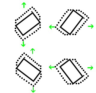
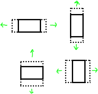
* Strong acceleration toward right, left, top, or bottom edge.

slide.png.1ff74f61173c21817aca7e5343fbfd0a.png

I think these are straightforward.  The gyro angles will remain basically stable, but acceleration will increase.  In the widescreen left/right shake I will get an acceleration that changes about (1, variable, 0).  Variable runs in the +/- 0.5 range, more or less depending on how fast it is moved. In the portrait up/down shake I will get changes of (0, variable, 0), where it starts at +1 or -1 depending on which way is up, then shifts by up to about 0.5 depending on motion direction.  All of those when rotations are basically constant.

In the widescreen up/down shake I will get (variable, 0, 0), in the portrait shake I will get (variable, 1, 0), with rotation angles basically constant.

Each of these can set the the flag to right, left, top, or bottom.


rotation.png.e33b2e1aeb70ad3811ca5b95018b45f1.png

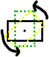
This one I can tell because the Z axis changes, but the magnitude of the acceleration vector remains basically constant at 1.0

This one can pull out rotation easily.

Now for the hard ones:

rotatedmotion.png.89c8543f6af8e09b3dfccd91a0ee97cf.png

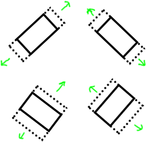
These, my intuition tells me at rest I should be seeing ( 0.7, 0.7, 0 ) with various sign differences, and acceleration variance for both axis, while the rotation angle remains basically constant.

However, I'm not easily able to figure out (in my brain) which is witch. I suspect I can come up with the answer by wrapping my brain around it for a few hours, but if someone can save me time because they know it offhand, that would help.

I'm looking for an easy way to detect acceleration toward top edge, bottom edge, right edge, or left edge, regardless of orientation.


It is this one that has me stumped:

moveThroughArc.png.5011f8709b8617c04721665f3949ee76.png

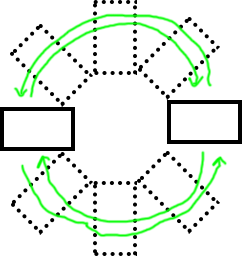
I want to be able to tell when large sweeping arcs are made. These are different from in-place rotation that is spinning only. These I'd like to show up as right-edge or left-edge, but they aren't detecting well at all because the forces are continuously varying.

My math history tells me something to do with atan2 on the X acceleration versus Y acceleration to tell me the direction, and then with some handwaving using the current Z direction, the result is I can tell which direction it is moving.

Any guidance here?


I'll probably be hammering away at the math for a few days as the hobby project allows only a few hours on nights and weekends.  Any insights to help shorten that time is greatly appreciated.

Advertisement

For the non-game project, here's the type of kite I'm attaching it to:  https://www.youtube.com/watch?v=91kk3T4cDbI


Here's a video of the prototype motions, before hooking up to acceleration data:


This is VERY cool!  Wish I could help with the math..  I would probably build some kind of rig to hold the device at the desired angle and mimic the movement patterns so I could collect enough data to verify my math.  You might be able to rig up something suitable with a couple thrift-store camera tri-pods and some nuts and bolts. ;)

The board is on my desk, the 3 meter line from the frame allows me to move it around and simulate it. But it is hard to watch numbers and move the sensors in a convincing pattern at the same time.  I normally fly on 40 meter / 120 foot lines, so the forces, timings, and distances will be hard to mimic. 

It means I can't reasonably get training data to throw it into an AI, which would be my first choice for recognizing the gestures.

I guess I could do all that work to simulate it and build an AI, or I could just ask about the math, and let math wizards help with the stuff I tried to purge from my brain way back in the nineteen hundreds. It's been two decades since graduation, so some of that is a little rusty. ?

In the sweeping arc case, I think you'll feel acceleration away from the center of the circle (centrifugal force). So like the portrait up/down shake, (0, variable, 0), where variable is a fairly stable value, either positive or negative depending on which way you're spinning. But there will also be a varying gravity vector added to it, and I'm not sure offhand how to separate that out. The gyro will give you the rotation rate, but that will be indistinguishable from spinning-in-place.

In the angled shaking case, you are correct that at rest you should see ( 0.7, 0.7, 0 ) with sign flipping depending on which orientation it is. But when shaking, only one axis will vary, same as in landscape or portrait orientation.

Now if you shake up/down/left/right while in angled orientation like this, you will get two axis variation:

Diagram.png.e43c136671a789a389057fe0b8ba7d5c.png

But that may not be needed for your application.

Another thing to be aware of is an awesome sensor called BNO055, which has 3-axis accelerometer, gyro, and compass sensors, and some very clever programming to sort out the absolute orientation of the sensor with respect to the earth (the 3 axes are east/west, north/south, up/down), and separates out the gravity vector from other acceleration (this is the part that would be most useful in your case). You can probably get by without it for this project, but it might make things easier.

From playing with the math more, I'm thinking these are right:   angleAccel = atan2(accX, accY + abs(accZ));

think those give me the angle of the acceleration. 

Desk checking that, a motion of (positive,0,0) facing upright gives 90 degrees or up, and (negative, 0, 0) gives -90 degrees or down.  (0, positive, 0) gives 0 degrees or right facing, (0, negative, 0) gives 180 degrees or left facing. (The answers are radians, so actually 1.57, 0, 3.14, etc.)

Moving diagonally, a motion of (n, n, 0) for each positive/negative variation looks like the correct angle.

With that in place, I can compare the angle of acceleration against the axisZ. 


So that gives these:


// If the magnitude of the acceleration vector is 1 regardless of orientation, then it is probably stationary,
// but might be turning while falling with a net for equal to 1G.
if( near( 1.f, magnitude( accX, accY, accZ) ) {
  if( changing ( axisZ ) && changingSameRate( axisZ, angelAccel) ) { /* is rotating in place */ }
  else { /* falling while rotating */ }
}
else // Not exactly 1G forces, so probably moving...
{
  // If the axisZ remains stable then the motion isn't a turn, it's a slide.
  if( changing ( axisZ ) ) { /* is rotating while moving, NEED MORE MATH HERE? */ }
  else { /* axisZ isn't changing, so we must be sliding without turning */ }
}

I think in the NEED MORE MATH HERE section, if the magnitude is >1 then it is probably accelerating through an arc, and I can determine if the arc is CW or CCW by which direction axisZ is changing.

I feel like I'm still missing various cases with this.

Thinking more on this, accelerating downward around a circle might be problematic.  The acceleration vector can be less than 1 because it is doing a controlled fall, and it is rotating over time. I can probably use the math above, but the rotation won't appear continuous.

I think it will soon be time to rig up some practical, experimental tests.


Aorry to not answer any qestion and for giving useless clues, but if the weight is not that much problem maybe you could connect arduino to the phone itself (it can be wuite problematic due to all security patches manufacturers provide so simple stupid user wont damage its phone after 1 h of usage) then you could use neural networks, and ease your calculations.

As for other questions maybe you could write another post with less data and do one thing at a time i have a hard time to understand any of the problems, so maybe post one thing you want to achieve then when given aoltuion write another reply here for the next problem, this would solve problems faster.

Its not that i font understand the oriiginal post but have not that much time to dig into it

There's tons of IMU code on line from drone people.

http://x-io.co.uk/open-source-imu-and-ahrs-algorithms/

Cool project Frob :).

On 1/28/2019 at 1:13 AM, frob said:

I'm looking for an easy way to detect acceleration toward top edge, bottom edge, right edge, or left edge, regardless of orientation.

I think you sort of have that already, your accelerometer seems to be local to the kite. Gravity is sort of hiding that, so to make it easier for yourself you can take it out of the equation. I'm guessing your can build an orientation matrix from gyroscopic data, if you multiply that with the gravity vector and subtract that from your accelerometer data you should be getting something close to (0, 0, 0) when the kite isn't moving. Moving it left/right, up/down or back/forth should then respectively result in only one of the components changing (minus some noise).

As for detecting sweeping arcs, I think it's easiest to transform the accelerations to 'world' coordinates and check how the direction of the acceleration changes over time. The reason you want world coordinates is that local acceleration can be constant while moving in a curve (e.g. a satellite that orbits the earth).

This topic is closed to new replies.

Advertisement