@Zakwayda
I had to just change some minor things, to fit into my existing class and to use the DirectX vector math, but overall it's the same function. The reason it only has one box in the argument is because it compares that box to the internal box that's represented by the class. I tried looking over the code, but it's just a jumble of cross products, I don't feel like I know enough about it to start simplifying/optimizing it to fit my needs. Here is what it looks like after my changes:
bool CollisionBox::mGetSeparatingPlane(const XMVECTOR& RPos, const XMVECTOR& Plane, const XMVECTOR& AxisX, const XMVECTOR& AxisY, const XMVECTOR& AxisZ, const XMVECTOR& Extents)
{
	XMFLOAT3 ExtentsF;
	XMStoreFloat3(&ExtentsF, Extents);

	XMVECTOR PosPlaneDot = XMVector3Dot(RPos, Plane);
	XMFLOAT3 PosPlaneDotF;
	XMStoreFloat3(&PosPlaneDotF, PosPlaneDot);

	XMVECTOR XAxisPlaneDotSelf = XMVector3Dot(mXAxis*mXExtent, Plane);
	XMFLOAT3 XAxisPlaneDotSelfF;
	XMStoreFloat3(&XAxisPlaneDotSelfF, XAxisPlaneDotSelf);

	XMVECTOR YAxisPlaneDotSelf = XMVector3Dot(mYAxis*mYExtent, Plane);
	XMFLOAT3 YAxisPlaneDotSelfF;
	XMStoreFloat3(&YAxisPlaneDotSelfF, YAxisPlaneDotSelf);

	XMVECTOR ZAxisPlaneDotSelf = XMVector3Dot(mZAxis*mZExtent, Plane);
	XMFLOAT3 ZAxisPlaneDotSelfF;
	XMStoreFloat3(&ZAxisPlaneDotSelfF, ZAxisPlaneDotSelf);

	XMVECTOR XAxisPlaneDotOther = XMVector3Dot(AxisX*ExtentsF.x, Plane);
	XMFLOAT3 XAxisPlaneDotOtherF;
	XMStoreFloat3(&XAxisPlaneDotOtherF, XAxisPlaneDotOther);

	XMVECTOR YAxisPlaneDotOther = XMVector3Dot(AxisY*ExtentsF.y, Plane);
	XMFLOAT3 YAxisPlaneDotOtherF;
	XMStoreFloat3(&YAxisPlaneDotOtherF, YAxisPlaneDotOther);

	XMVECTOR ZAxisPlaneDotOther = XMVector3Dot(AxisZ*ExtentsF.z, Plane);
	XMFLOAT3 ZAxisPlaneDotOtherF;
	XMStoreFloat3(&ZAxisPlaneDotOtherF, ZAxisPlaneDotOther);


	return (fabs(PosPlaneDotF.x) >
		(fabs(XAxisPlaneDotSelfF.x) +
			fabs(YAxisPlaneDotSelfF.x) +
			fabs(ZAxisPlaneDotSelfF.x) +
			fabs(XAxisPlaneDotOtherF.x) +
			fabs(YAxisPlaneDotOtherF.x) +
			fabs(ZAxisPlaneDotOtherF.x)));
}
The above function is called by the other function listed below, which does all the heavy lifting:
bool CollisionBox::mCheckForCollision(const CollisionBox& box)
{

	//static XMVECTOR RPos;

	XMVECTOR RPos;
	RPos = box.GetCenter() - mCenter;

	XMVECTOR XXCross = XMVector3Cross(mXAxis, box.GetXAxis());
	XMVECTOR XYCross = XMVector3Cross(mXAxis, box.GetYAxis());
	XMVECTOR XZCross = XMVector3Cross(mXAxis, box.GetZAxis());
	XMVECTOR YXCross = XMVector3Cross(mYAxis, box.GetXAxis());
	XMVECTOR YYCross = XMVector3Cross(mYAxis, box.GetYAxis());
	XMVECTOR YZCross = XMVector3Cross(mYAxis, box.GetZAxis());
	XMVECTOR ZXCross = XMVector3Cross(mZAxis, box.GetXAxis());
	XMVECTOR ZYCross = XMVector3Cross(mZAxis, box.GetYAxis());
	XMVECTOR ZZCross = XMVector3Cross(mZAxis, box.GetZAxis());


	return !(mGetSeparatingPlane(RPos, mXAxis, box.GetXAxis(), box.GetYAxis(), box.GetZAxis(), box.GetExtents()) ||
		mGetSeparatingPlane(RPos, mYAxis, box.GetXAxis(), box.GetYAxis(), box.GetZAxis(), box.GetExtents()) ||
		mGetSeparatingPlane(RPos, mZAxis, box.GetXAxis(), box.GetYAxis(), box.GetZAxis(), box.GetExtents()) ||
		mGetSeparatingPlane(RPos, box.GetXAxis(), box.GetXAxis(), box.GetYAxis(), box.GetZAxis(), box.GetExtents()) ||
		mGetSeparatingPlane(RPos, box.GetYAxis(), box.GetXAxis(), box.GetYAxis(), box.GetZAxis(), box.GetExtents()) ||
		mGetSeparatingPlane(RPos, box.GetZAxis(), box.GetXAxis(), box.GetYAxis(), box.GetZAxis(), box.GetExtents()) ||
		mGetSeparatingPlane(RPos, XXCross, box.GetXAxis(), box.GetYAxis(), box.GetZAxis(), box.GetExtents()) ||
		mGetSeparatingPlane(RPos, XYCross, box.GetXAxis(), box.GetYAxis(), box.GetZAxis(), box.GetExtents()) ||
		mGetSeparatingPlane(RPos, XZCross, box.GetXAxis(), box.GetYAxis(), box.GetZAxis(), box.GetExtents()) ||
		mGetSeparatingPlane(RPos, YXCross, box.GetXAxis(), box.GetYAxis(), box.GetZAxis(), box.GetExtents()) ||
		mGetSeparatingPlane(RPos, YYCross, box.GetXAxis(), box.GetYAxis(), box.GetZAxis(), box.GetExtents()) ||
		mGetSeparatingPlane(RPos, YZCross, box.GetXAxis(), box.GetYAxis(), box.GetZAxis(), box.GetExtents()) ||
		mGetSeparatingPlane(RPos, ZXCross, box.GetXAxis(), box.GetYAxis(), box.GetZAxis(), box.GetExtents()) ||
		mGetSeparatingPlane(RPos, ZYCross, box.GetXAxis(), box.GetYAxis(), box.GetZAxis(), box.GetExtents()) ||
		mGetSeparatingPlane(RPos, ZZCross, box.GetXAxis(), box.GetYAxis(), box.GetZAxis(), box.GetExtents()));

}
Neither of those are exposed, the public function that interfaces with the other code is this:
bool CollisionBox::checkForCollision()
{

	for (CollisionBox* box : mCollisionBoxList)
	{
		if (box == this)
			continue;


		if (mCheckForCollision(*box))
			return true;
	}

	return false;
}
15 hours ago, Zakwayda said:
Not so much. The center is a specific reference point - the geometric center of the box. (It's the point you'd most likely intuitively think of as the 'center of the box'.)
It's the geometric center of the box? But how?
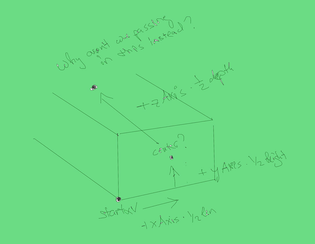
XMVECTOR center = startXZv + xAxis * xExtent + yAxis * yExtents;
Starting at point0 and moving down 1/2 of the x axis and then moving up 1/2 the y axis don't we just end up on the face of the box? Can you take a look at the picture and see where I'm getting it wrong? Don't we need to have the zAxis * zExent to get the geometric center of the box? But even at the moment, my center is defined as
XMVECTOR center = startXZv + xAxis * xExtent;
I had to remove the y component to lower it to the ground, but the SAT is still working fine, why is that?
This is the picture of how I understand it:
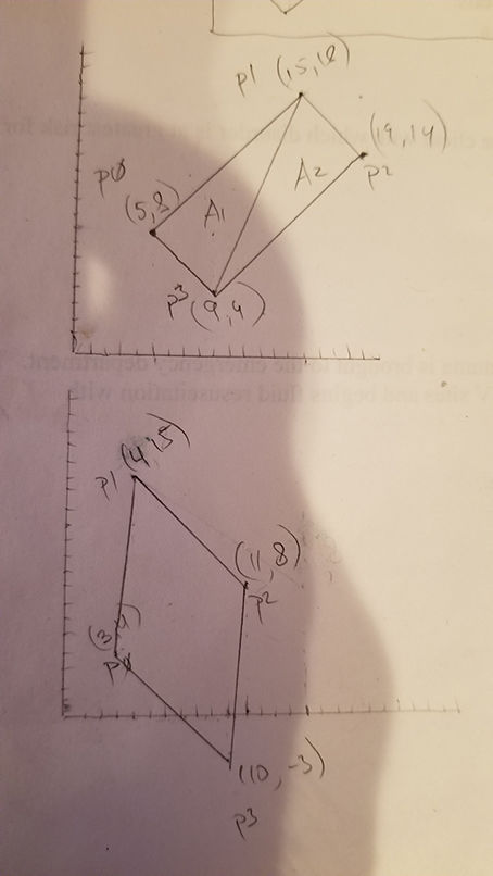
Also you can you see how my collision boxes are still miss-aligned? It's because of the center coordinate offset I believe: