Linear interpolation of two vector arrays with different lenghts

Started by
54 comments, last by ManitouVR 4 years, 6 months ago

@alvaro @Zakwayda

3 hours ago, alvaro said:
Whatever happened to the idea of keeping the times associated to the points through the smoothing steps?
 
1 hour ago, Zakwayda said:
So, why aren't you doing this as part of the smoothing process?
 
Hello and thanks for your feedback guys.
Well, i actually did what everybody told me to do. And the idea of doing the retiming never went away.
I even optimized the existing smoothing functions already to accept my struct, so that i can include the retiming and pressure calcs as well.
But if somebody (alvaro) is already so kind to spend time, knowledge and effort to help me, then i can not just say:"No".
I mean how rude and impolite would that be?? Also nobody knew how well it would perform. So maybe it would have been sufficient.
 
Now that we know better i will move on with the retiming as part of the smoothing.
So at the moment iam at the stage where the RDP function spits out some leftovers with xy's and the proper time values.
How will i continue from here?
 
Quote

but are you evaluating a release build?

Yes


3D Artist

Advertisement
32 minutes ago, C3D_ said:

So at the moment iam at the stage where the RDP function spits out some leftovers with xy's and the proper time values.

How will i continue from here?

The short answer is that every time the smoothing code interpolates between two points from the input curve, you should interpolate the other relevant parameters (time, pressure, etc.) as well using the same interpolation value. (If any of the algorithms you're using do something other than simple interpolation, things might be more complicated.)

I think I suggested this earlier as well, but I'd suggest tackling each step of the smoothing process (RDP, corner-cutting, and resampling or whatever) separately. It might be useful to set up your code so that you can turn the different steps on and off, allowing you to, for example, only use RDP and skip the other steps. Then you can test the steps in isolation and see if what you're doing is working so far.

Since preserving the ancillary values with RDP appears to be trivial, it seems corner-cutting is the next step to tackle. Again, you'll want to find the places in the algorithm where points are interpolated, and revise the code so that the other parameters are interpolated as well.

If that's not clear, then I'd suggest posting your code for the corner-cutting algorithm so that someone can maybe point you in the right direction.

@Zakwayda Okay got you!
RDP is done already. So now i try to find the places in the Chaikin function.
I will report back. Thank you! ?
 

struct Vertex
{
	double x;
	double y;
	unsigned int p;
	unsigned int t;
	sf::Color c;
	// Constructor
	Vertex(double x, double y, unsigned int p, unsigned int t, sf::Color c) : x(x) , y(y) , p(p), t(t), c(c) {}
};

//---------------------------------------------------------------------------------------------
// Chaikin - Corner Cutting (Smoothing by corner cutting)
//---------------------------------------------------------------------------------------------

std::vector<Vertex> Smooth(std::vector<Vertex> &IN, int iterations)
{
	size_t VC = IN.size();
	if (VC < 2) { return IN; }

	sf::Vector2f startp = sf::Vector2f(IN[0].x, IN[0].y);
	sf::Vector2f Endpnt = sf::Vector2f(IN[VC - 1].x, IN[VC - 1].y);
	std::vector<Vertex> OUT = IN;

	for (int i = 0; i < iterations; i++)
	{
		size_t VCount = OUT.size();
		
		std::vector<Vertex> newCurve;
		
		newCurve.emplace_back(startp.x, startp.y, 0, 0, sf::Color::Black);

		for (int j = 0; j < VCount - 1; j++)
		{
			sf::Vector2f displacem = sf::Vector2f(OUT[j + 1].x - OUT[j].x, OUT[j + 1].y - OUT[j].y);
			sf::Vector2f newPoint1 = sf::Vector2f(OUT[j].x + (0.25f * displacem.x), OUT[j].y + (0.25f * displacem.y));
			sf::Vector2f newPoint2 = sf::Vector2f(OUT[j].x + (0.75f * displacem.x), OUT[j].y + (0.75f * displacem.y));

			newCurve.emplace_back(newPoint1.x, newPoint1.y, 0, 0, sf::Color::Black);
			newCurve.emplace_back(newPoint2.x, newPoint2.y, 0, 0, sf::Color::Black);
		}

		newCurve.emplace_back(Endpnt.x, Endpnt.y, 0, 0, sf::Color::Black);
		OUT = newCurve;
	}
	return OUT;
}


3D Artist

Okay, iam through with Chaikin now and i get interpolated times from this function as well now.
I just fear that the playback will look very linear since A LOT of time data gets lost in the RDP step.
However, i will move on to the curve resampling (evenly distribute) function now.
Lets see if i make it through without help, haha!
Here are the additional changes i made...

struct Vertex
{
	double x;
	double y;
	unsigned p;
	double t;
	sf::Color c;
	// Constructor
	Vertex(double x, double y, unsigned int p, double t, sf::Color c) : x(x) , y(y) , p(p), t(t), c(c) {}
};

// In the function

double timeStartp = IN[0].t;
double timeEndpnt = IN[VC - 1].t;


double duration = (OUT[j + 1].t - OUT[j].t);
double time1 = OUT[j].t + (0.25f * duration);
double time2 = OUT[j].t + (0.75f * duration);


3D Artist

3 hours ago, C3D_ said:
I just fear that the playback will look very linear since A LOT of time data gets lost in the RDP step.

Aha - we finally found a way in which a post-processing step may fare better than doing the interpolation as part of the smoothing.

However, all may not be lost. Here:


RamerDouglasPeucker(PLin, 3.0, PLOut);

You have the opportunity to specify a tolerance for the RDP algorithm ('3' in the above example). You might try some different tolerance values to see if you can get the RDP step to retain more of the original data.

There may be a conceptual problem though. You could draw a roughly straight line of points with varying speed (or pressures or whatever), and RDP probably is simply going to discard that data more or less irrespective of the tolerance value, because RDP only considers geometry and doesn't care about the ancillary data. So in a perfect world, it seems you'd want something like this: only simplify parts of the curve that are relatively linear and for which the ancillary data deltas are fairly consistent.

I have a vague idea about revising RDP to treat the ancillary data as additional spatial dimensions, and computing the distances in that space, meaning that significant changes in delta values would register as 'curviness' and cause that part of the curve not to be simplified. But I'm speculating (I'd need to think about it some more and test it out myself to have any confidence in that idea).

It also might be worth considering that if your last smoothing step adds in new points where RDP previously removed points, there might be little point in running RDP at all. Another possible question to ask is if the smoothed paths are actually in some way more to your liking than the originals. Are all the smoothing steps actually necessary? Could you just use the original points? Or maybe just run corner-cutting but not the other steps?

The post-processing step is tempting, but the complexity (and therefore execution time) when you have hundreds or thousands of points seems like an obstacle. My intuition is that the smoothing algorithms could be further revised to preserve more of the original ancillary data when the deltas are irregular, but I admit that that would be a less straightforward change to make than what I've been suggesting so far.

I thought a little more about the problem of losing relevant data with RDP. I'll discuss the speed issue here, but I think the same concept can be applied to other parameters, like pressure.

The following is speculative and off the top of my head, and there may be errors (conceptual or otherwise).

Each segment in the original curve has a speed, which can be computed as (p0 and p1 are the endpoints of the segment):


distance(p0, p1) / (p1.absolute_time - p0.absolute_time)

Every point but the first and last can then be given a 'speed delta' value that is the absolute value of the difference between the speeds for the segments preceding and following the point. The greater this value, the more 'important' this point is (irrespective of other factors) in terms of capturing information about the original drawing speed.

Here's a concrete example:


 speed delta = abs(5-5) = 0
             |
             v
*------------*------------*
   speed=5      speed=5

In this case you could remove the middle point without losing any information regarding speed. However, in this case:


 speed delta = abs(9-1) = 8
             |
             v
*------------*------------*
   speed=1      speed=9

Losing the middle point would lose valuable information, turning a period of slow movement followed by a period of quick movement into a single, uniform average speed. This seems to be the problem you're describing, where your RDP implementation is losing this kind of information.

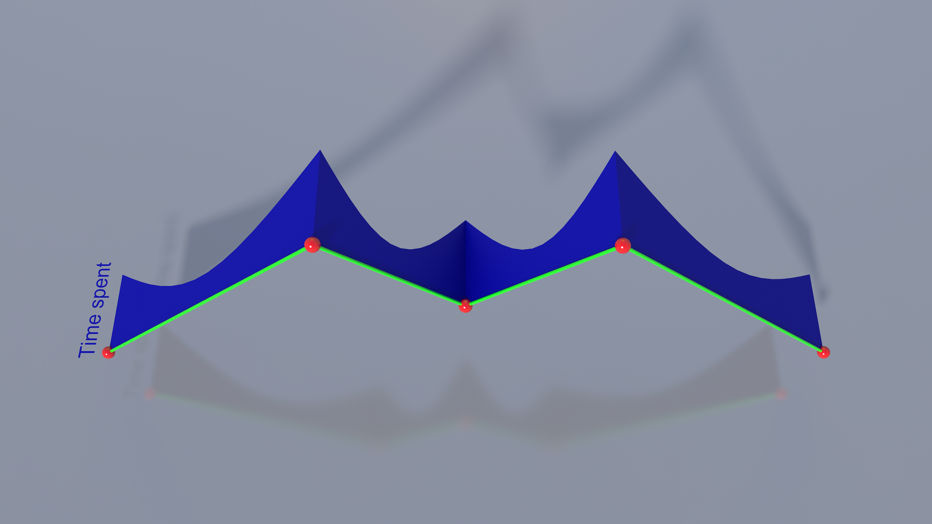
What I'm wondering is if the dimension in which the RDP algorithm is run could be expanded to include other parameters. So that we don't have to think beyond 3-d, let's just stick to one extra parameter, speed. Imagine the geometric curve lying in the xy plane. Now, map the speed deltas to the z axis in 3-d, so you have a 3-d curve. If RDP is then run in 3-d, incorporating this new information, the speed deltas can help prevent points that represent important speed information from being lost.

One factor here is scale. If the speed deltas are much smaller or larger in general than the geometric deltas, that could throw things off, giving the speed deltas too little or too much weight. A possible solution would be to include a scaling/weighting factor for the speed deltas (and any other additional parameters you wish to include) so that the contribution is appropriately proportional.

In summary, although I'm not sure I've worked out all the details here, I think it still may be possible to get the results you want by modifying the smoothing algorithm(s) (and given the possible expense of post-processing, that may be the only practical option).

@Zakwayda I'am trough now with the "evenly distribute" function as well. So actually iam done with all steps now.
 
Iam very well aware of the RDP functions epsilon / reduction strenght feature. i set it to 3.0 myself. I really do need this feature!
I want, in the final software, to be able to choose the strenght of the smoothing with a slider. Just like in Illustrator.
This helps A LOT to smoothen out shaky hand drawings my it be from a shaky hand or from a crappy graphics tablet jitter.
 
2 hours ago, Zakwayda said:
Aha - we finally found a way in which a post-processing step may fare better than doing the interpolation as part of the smoothing.
Haha! I was not looking for a way to escape the "calc time through smoothing steps", programming effort lol. I just noticed the fact so i pointed it out.
 
Thanks for pointing out a new possible solution to the RDP reduction "problem". Before i look into that i would like to get an honest opinion
from you or anybody interested about the natural look of the playback.
I made a new video HERE . So i would be curious about others opinions if the playback looks natural like the input.
For me it looks better than expected.  ?
3 hours ago, Zakwayda said:

There may be a conceptual problem though. You could draw a roughly straight line of points with varying speed (or pressures or whatever)

Exactly the same thought crossed my mind as well. I wouldnt be too concerned about the playback but more about the pen pressure side.

3D Artist

6 minutes ago, C3D_ said:
I made a new video HERE . So i would be curious about others opinions if the playback looks natural like the input.

It certainly looks just fine, and very natural. It you were to put the original and the 'replay' side by side instead of in sequence one might be able to spot inaccuracies with respect to speed, but shown in succession there certainly don't seem to be any problems.

Of course as long as the path is sufficiently 'curvy', your algorithms are probably going to do fine with the timing. A problem case would be more like the one I described earlier, where the user draws a more or less straight line, but with varying speed. As for your video though, seems good to me ?

1 hour ago, Zakwayda said:

Imagine the geometric curve lying in the xy plane. Now, map the speed deltas to the z axis in 3-d, so you have a 3-d curve.

You mean like this?

1729671010_2Dcurve3Dtime.thumb.png.869f03ab039f4d86b18ceadb3f03ca75.png

@Zakwayda Thanks for your positive feedback. I also think that its sufficient. And even if its a straight line... it doesent really matter. One could just have drawn the straight line in one wipe. As long as the overall look does not look robotic iam okay with it! :)

3D Artist

Quote

You mean like this?

Did you just make that? If so, nice. If in that example the red points lie in a plane and the blue part is perpendicular to that plane, then yeah, that's close to what I mean. The only difference is that in my example the time information is reduced to a single value for each point, so the blue part would be angular rather than curved and would only have vertices where there are red points. (Also, it wouldn't be 'time spent' exactly but rather information about changes in speed.) RDP would then be run on the vertices of the blue part, which, theoretically at least, would account for both the curve geometry, and changes in speed.

That said:

Quote

I also think that its sufficient. And even if its a straight line... it doesent really matter. One could just have drawn the straight line in one wipe. As long as the overall look does not look robotic iam okay with it!

If that's the case, it sounds like maybe your problem is essentially solved and the extra complexity may not be needed :)

This topic is closed to new replies.

Advertisement