Hi all,
How can I implement simple 3D polygon modelling? I have a small 3D engine( https://twitter.com/ongamex92/status/1159194667067617281?s=20 ) of mine and since a little kid I wanted to implement polygon modelling like all DCCs, extruding faces, inset, bevel and so on.
I'm not looking to replace 3ds Max or Blender or course ![]() I just want to implement it.
I just want to implement it.
I'm looking for tips and pointers and articles on how to approach it, but I cannot find any pieces of this arcane knowledge.
All tips and suggestions are welcome.
How can I implement simple 3D polygon modelling?

Author

I would advice some scripting in 3ds max, this will reveal the underlying data and system design they have. The documentation is good.
Check the box engine in C, attempting to have a community engine with that kind of knowledge, that company's have but people can't access the information.
Already find a lot o information.
Attempting to doing something like that, create models with code, so we don't need complex functionality. The code will do that for us.
It will probably something easy to do.
Was thinking in a example: let's say we create adjust points, so a base of the foot have 2 curves, 2 lines, adjusting them we create different types. based on this we can apply to the rest parts of the body. Adding adjusting points.
Then it's probably a thing of create a average set of points, for a lady style it have x proportions, for a male z proportions, etc…
the lady have hips + 20% then male, male + 20% musculus, click and it's done.
For a car, let's say wheels, 2 circles, +1 inside for rims. In this probably the adjusting point is where it bends. Adjust click auto generate wheels.
Once we store the proportions then we can automate stuff. We know that top line have x proportions. All human foots will be more or less like that…

ongamex92 said:
How can I implement simple 3D polygon modelling? I have a small 3D engine( https://twitter.com/ongamex92/status/1159194667067617281?s=20 )
Looks you do not need to use an ‘upcoming engine’ written by someone else with very questionable knowledge ; )
Implementing mesh editing is far from trivial. I did it two times, once with thy same goal you have actually (manual modeling), and the second time for automated geometry processing (and here i learned what i did wrong the first time.)
What you need to get right is the data structure representing the graph of a mesh. If you make a wrong decision here initially, you easily get to the point where you have to rewrite everything, but realizing this very late.
Until today i have not found a solution here that leads to intuitive code. Likely there is no way to make it easy and avoid tedious work, but this are the options i have tried:
Indexed meshes like used in game engine for rendering. That's not really an option because it misses adjacency information - you do not know what polygons are at a vertex or edge.
You need ability to traverse the components of a mesh in clockwise (or counter clockwise) order. That's the key, and the problem is to maintain the necessary data structure when changing the topology of the mesh.
So i solved this using std::vectors for this things: Ordered triangles around a vertex, ordered edges around a vertex, for each edge 2 vertices and 2 polygons, also in order. For each polygon a vector of ordered edges.
This worked, but it takes a lot of memory, does many dynamic allocations, and maintaing all this when editing the mesh is lots of work and error prone.
Next step was to adopt the Half Edge data structure, which is commonly used. I still use it and so far i'm happy with it. This blog was very helpful for me: https://kaba.hilvi.org/homepage/blog/halfedge/halfedge.htm
There are also open source frameworks like https://www.openmesh.org/media/Documentations/OpenMesh-6.3-Documentation/a00010.html or https://doc.cgal.org/latest/HalfedgeDS/index.html which i have no experience with.
Mesh editing code became less complex, but also less intuitive. Somebody not familiar with the data structure can't read it easily. Memory requirements are very good, no need for dynamic sized vectors - instead you traverse the mesh using edges to get clockwise order.
So i would recommend to get started with this, even if it seems overkill at the first look.
There are alternatives (e.g. https://en.wikipedia.org/wiki/Winged_edge), but i doubt it really helps to make things easier - there just is that complexity we need to tackle in one way or the other.
That said, here is how my header file looks like which contains the necessary base functionality to do things like remeshing, quadrangulation etc.:
	class HEMesh_Modeling : public HEMesh
	{
	public:

		int AddPolygon (const int edge,
			const int atIndex = -1);

		int AddPolygonFromEdges (const int *edgeIndices, const int numEdges,
			const int atIndex = -1);

		int AddPolygonFromVertices (const int *vertexIndices, const int numVertices,
			const int atIndex = -1);

		void RemovePolygon (const int poly);

		void CompactPolygons ();


		int AddEdge (const int vertex0, const int vertex1,
			const int atIndex = -1, const int pairAtIndex = -1,
			bool debug = false);

		int TessellateEdge (const int edge, const int tess);

		bool IsCollapseableEdge (const int edge, int *data = 0);
		int CollapseEdge (const int edge);

		bool PrepareEdgeRotation (std::vector<int> &edgeLoop, int (&targetLoop)[2],
			const int edge, const int vertex0, const int vertex1);
		bool RotateEdge (const int edge, const int vertex0, const int vertex1);

		int RemoveFreeEdge (const int edge);

		int RemoveEdge (const int edge);

		bool Check_MergeOpenEdges (const int edge0, const int edge1) const;
		bool MergeOpenEdges (const int edge0, const int edge1);

		void CompactEdges (std::vector<int> &compactIndirection);
		void CompactEdges ()
		{
			std::vector<int> compactIndirection;
			CompactEdges (compactIndirection);
		}


		int AddVertex (const vec &pos);

		bool RemoveVertex (const int vertex);

		bool CheckMergeOpenVertices (
			int &dstBeginEI, int &srcEndEI, // first pair of edges to merge
			int &srcBeginEI, int &dstEndEI,
			const int dstVertex, const int srcVertex,
			const bool prepare = false); // modify edge vertices
		bool MergeOpenVertices (const int dstVertex, const int srcVertex);

		void CompactVertices (std::vector<int> &compactIndirection);
		void CompactVertices ()
		{
			std::vector<int> compactIndirection;
			CompactVertices (compactIndirection);
		}

		template <typename T>
		static void CompactDataVector (std::vector<T> &dataVector, const std::vector<int> &indirection)
;


		void Compact ()
		{
			CompactEdges();
			CompactPolygons();
			CompactVertices();
		};
… just to give you an idea how ugly and non-intuitive this crap is. Here one example implementation:
int HEMesh_Modeling::AddEdge (const int vertex0, const int vertex1,
			const int atIndex, const int pairAtIndex,
			bool debug)
{
//if (vertex0==7 && vertex1==27) debug = true;
if (debug)
{
	RenderCircle(0.1f, GetVertexPos(vertex0), vec(0,0,1), 1,0,0);
	RenderCircle(0.1f, GetVertexPos(vertex1), vec(0,0,1), 0,1,0);
}

	assert (vertex0!=-1 && vertex1!=-1);
	if (vertex0 == vertex1) return -1;
	if (atIndex==-1 && pairAtIndex!=-1) return -1;
	if (atIndex!=-1 && pairAtIndex==-1) return -1;

	int newEIa = atIndex;
	int newEIb = pairAtIndex;
	bool addEdges = false;
	if (atIndex==-1)
	{
		addEdges = true;
		newEIa = GetEdgeCount();
		newEIb = newEIa+1;
	}


	int vI0 = vertex0;
	int vI1 = vertex1;

	int eI0 = GetVertexEdge(vI0);
	int eI1 = GetVertexEdge(vI1);


	// both vertices unconnected?
	if (eI0==-1 && eI1==-1)
	{
		if (addEdges) SetEdgeCount(newEIa+2);

		SetEdgePair(newEIa, newEIb);
		SetEdgePair(newEIb, newEIa);

		SetEdgeNext(newEIa, newEIb);
		SetEdgeNext(newEIb, newEIa);

		SetEdgeVertex(newEIa, vI0);
		SetEdgeVertex(newEIb, vI1);
		SetEdgePoly(newEIa, -1);
		SetEdgePoly(newEIb, -1);

		SetVertexEdge(vI0, newEIa);
		SetVertexEdge(vI1, newEIb);

		return newEIa;
	}


	bool swapped = false;
	if (eI0==-1 && eI1!=-1)
	{
		std::swap(vI0, vI1);
		std::swap(eI0, eI1);
		swapped = true;
	}

	assert(eI0!=-1);

#if 0
	bool isBoundaryLoop = true;
	int eIv0 = -1;
	int eIv1 = -1;
	int eI = eI0;

	// todo: replace boundary traversal with FindOpenEdgeBetween?
	do {
if (debug) ((HEMesh_Vis*)this)->RenderEdgeConnectivity(eI, 1,1,0, 0.04f);
		if (GetEdgePoly(eI)!=-1)
			isBoundaryLoop = false;
		int nextEI = GetEdgeNext(eI);
		int vI = GetEdgeVertex(nextEI);
		if (eIv0 == -1 && vI == vI0) eIv0 = eI;
		if (eIv1 == -1 && vI == vI1) eIv1 = eI;
		eI = nextEI;
	} while (isBoundaryLoop && eI != eI0);

	if (!isBoundaryLoop)
		return -1;
//*
	eI = eI1;
	if (eI1!=-1 && (eIv0==-1 || eIv1==-1)) do {
if (debug) ((HEMesh_Vis*)this)->RenderEdgeConnectivity(eI, 0,1,1, 0.04f);
		if (GetEdgePoly(eI)!=-1)
			isBoundaryLoop = false;
		int nextEI = GetEdgeNext(eI);
		int vI = GetEdgeVertex(nextEI);
		if (eIv0 == -1 && vI == vI0) eIv0 = eI;
		if (eIv1 == -1 && vI == vI1) eIv1 = eI;
		eI = nextEI;
	} while (isBoundaryLoop && eI != eI1);

	if (!isBoundaryLoop)
		return -1;
//*/
	if (eIv0==-1)
		return -1;

if (debug)
{
	ImGui::Text("%i %i - %i %i", eI0, eIv0, eI1, eIv1);
	ImGui::Text("%i %i - %i %i", eI0, FindEdgePrev(eI0), eI1, FindEdgePrev(eI1));
}
#else
	int eIv0 = FindEdgePrev(eI0);
	int eIv1 = (eI1==-1 ? -1 : FindEdgePrev(eI1));
#endif


	// only one vertex connected?
	if (eI1==-1)
	{
		int prevEIa = eIv0;
		int nextEIb = GetEdgeNext(eIv0);

		if (addEdges) SetEdgeCount(newEIa+2);

		SetEdgePair(newEIa, newEIb);
		SetEdgePair(newEIb, newEIa);

		SetEdgeNext(prevEIa, newEIa);
		SetEdgeNext(newEIa, newEIb);
		SetEdgeNext(newEIb, nextEIb);

		SetEdgeVertex(newEIa, vI0);
		SetEdgeVertex(newEIb, vI1);
		SetEdgePoly(newEIa, -1);
		SetEdgePoly(newEIb, -1);

		SetVertexEdge(vI1, newEIb);

		return swapped ? newEIb : newEIa;
	}


	// both vertices connected

	if (eIv1==-1)
		return -1;

	int prevEIa = eIv0;
	int nextEIa = GetEdgeNext(eIv1);
	int nextEIb = GetEdgeNext(eIv0);
	int prevEIb = eIv1;

	if (addEdges) SetEdgeCount(newEIa+2);

	SetEdgePair(newEIa, newEIb);
	SetEdgePair(newEIb, newEIa);

	SetEdgeNext(prevEIa, newEIa);
	SetEdgeNext(newEIa, nextEIa);
	SetEdgeNext(prevEIb, newEIb);
	SetEdgeNext(newEIb, nextEIb);

	SetEdgeVertex(newEIa, vI0);
	SetEdgeVertex(newEIb, vI1);
	SetEdgePoly(newEIa, -1);
	SetEdgePoly(newEIb, -1);

	return swapped ? newEIb : newEIa;
}
I left the comments and defines in so you can see i had some issues here. Super ugly, no? You can imagine writing this and getting it right is no fun. Special cases, indexing bugs, realizing there can happen another special case much later… Can be quite frustrating, i tell you!
However, once you have this, adding stuff like beveling / extruding is very easy in comparison and fun / satisfying to do.
But think twice if you really want to go there. Is it worth the time, considering blender is free? Could you learn something more useful in that time?… Don't wanna sound demotivating ofc., just to give you some idea what it means.
Author
wow guys, thank you!
it is late at night here, but I'm eager to read everything on the topic tomorrow!
I take my recommendation back to use half-edge.
There is this case that just bothers me right now, and it is not the first time:
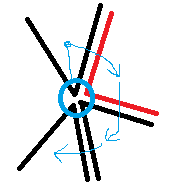
This are 4 triangles sharing the blue vertex.
Per vertex, half-edge only has a single pointer to one triangle, and from that you can traverse around the vertex (light blue arrows). But this causes the limitation that one vertex can only lie on one open boundary of the mesh.
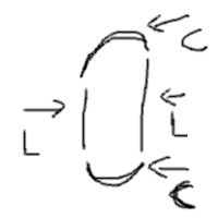
Imagine the user wants to draw this configuration like in the picture, which is valid, but he draws the black triangles first and the red triangle the last.
So before the red triangle is added, the configuration is invalid and can not be processed as usual - you can not find all triangles at the vertex easily.
And this causes bugs like infinite loops. Also, for manual editing this limitation might not be acceptable at all.
I guess modeling tools don't use half-edge but something else for such reasons. I did not have this problem with the std::vectors i've used before, but can't recommend this either. :\
I hope you have not already started to look into half-edge.
EDIT: After fixing my issues i see i remembered things somewhat wrong. Vertices store a pointer to an edge, not triangle, so traversing around the vertex is possible even with multiple open sections.
Sorry for tho noise - Half edge still recommended, but with restrictions.
My issue was cause by Assimp merging vertices so a non manifold case happened. This may or may be not a problem for modeling.
Imagine you ave a model of a sphere, pick one edge and you want to extrude a single quad out of the edge. This does not work with half-edge, because there is no valid edge order. Also the ring around vertex can not be flattened to a topological plane, so it's non manifold.
Most 3D editors allow to do something like this, indicating they use other data structures.
This topic is closed to new replies.
Advertisement
Popular Topics

Advertisement