very compact reflective shadow maps format

You could use normal 8-bits to store index just like MD2 format does. For encoding normal to index you need texture look up table. Just use x and y as texture coordinate and remember handle -z cases too. Decoding is really simple lookup table texture or uniform array.

Author
Ok I tried a few things, I'll make a report:
first, I coded a 16 bits storage scheme for color using this code:
effectively coding on 8/5/3 bits for RGB.
decoding, this way:
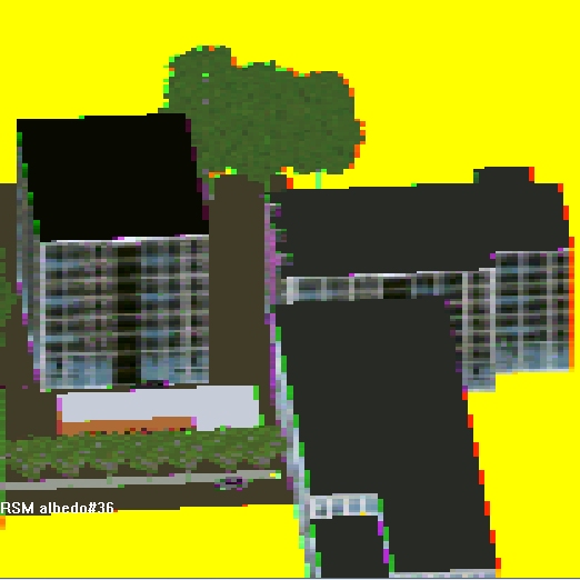
this is a 24 bit typical albedo image from sun point of view:

once encoded in 16 bits it gives:

so appart from the bug that makes whites yellow, there are no noticeable differences.
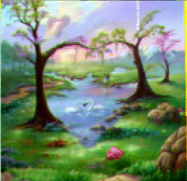
I have tried on a richer image, 24 bits:

once encoded in 16 bits, gives:

we see a bit of a loss in the sky: the gradient have now only 2 shades of blue, but it is barely noticeable.
so to go down to 8 bits we still need to separate storage into 2 pixels.
in the beginning I wanted to avoid to favor one direction (horizontal or vertical) so I went for "two diagonals" pattern:

so I did this code for encoding:
and this for decode:
and this gave:
which is almost acceptable because it was going to be used downsampled !
but I decided the unwanted parasite frequencies were dangerous for the stability of the light injection in the LPV cells.
so i went with the favor of vertical resolution, using the same encoding code, but a simpler reconstruction:
now we get:

which actually seems blurrier to the eye but we have the same amount of information.
however, while it looks totally OK on this image, back to our typical albedo image, we get a serious problem
(I forgot to copy this image, but you will be able to imagine from the next one)
the problem is that at high frequency regions, we get nasty chromatic errors. this is due to the fact that we are keeping channels of two different colors that we reconstruct and assign to 2 pixels. imagine a region passing from all white to all black, we get a terrible pink line and a green other one at the frontier.
To avoid this issue, I have thought of the "Pixel Quad Message Passing" paper from gpu pro2 that was mentioned above in the thread.
We can reconstruct the color of our neighbor pixel using ddx function:
the encoding shader becomes:
now the resulting image becomes:
which you don't know but it looks much better on the building windows. in the image without ddx we got lots of those pink and green lines instead of seeing ANY cyan color, that we perfect get here.
however my graphic card being and ATI (firegl 4800), every errors are not suppressed with that method. it could work better with nvidia, need to try. (cf PQA paper)
but this costed me a lot of time and I feel the gains are potentially Nil, because most cards are not limited by ROP/bandwidth output. For the moment I dropped this research, and went for dual render target with 24 bits color.
first, I coded a 16 bits storage scheme for color using this code:
outrsm.r = albedo_color.g;

outrsm.g = (bitsnap5(albedo_color.r) * 256. + bitsnap3(albedo_color.b) * 8.) / 255.;

float bitsnap5(float v)

{

  return floor(v * 32.) / 32.;

}

// same for bitsnap3 with 8
effectively coding on 8/5/3 bits for RGB.
decoding, this way:
clr.g = rsm.r;

clr.b = fmod(rsm.g * 256., 8.) / 8.;

clr.r = bitsnap5(rsm.g);
this is a 24 bit typical albedo image from sun point of view:
once encoded in 16 bits it gives:
so appart from the bug that makes whites yellow, there are no noticeable differences.
I have tried on a richer image, 24 bits:
once encoded in 16 bits, gives:
we see a bit of a loss in the sky: the gradient have now only 2 shades of blue, but it is barely noticeable.
so to go down to 8 bits we still need to separate storage into 2 pixels.
in the beginning I wanted to avoid to favor one direction (horizontal or vertical) so I went for "two diagonals" pattern:
so I did this code for encoding:
float2 txc = ScreenPosition.xy;

if (fmod(txc.x, 2) < 1)

{   // green components on even columns

  outrsm.albedo.r = albedo_color.g;

}

else

{   // red and blue components on odd columns

  outrsm.albedo.r = (bitsnap5(albedo_color.r) * 256. + bitsnap3(albedo_color.b) * 8.) / 255.;

}
and this for decode:
float4 ps_compact_albedo( PS_INPUT Input) : COLOR0

{

float c = SampleTex2dLod( Tex2DArg(DiffTexture), Input.Common.Texcoord.xy, 0.0f ).r;

float4 clr = (float4)0;

clr.a = 1;

float gsize = 256;

float4 globalRegionSize = float4(gsize,gsize,1/gsize,1/gsize);

float2 txc = Input.Common.Texcoord.xy * globalRegionSize.xy;

float c2;

if (fmod(txc.x, 2) < 1)  // even columns

{

  clr.g = c;  // green here is our green. rest is to lookup:

  if (fmod(txc.y, 2) < 1)

  {   // green component 1 -> look for blue red in down right diagonal

   c2 = SampleTex2dLod( Tex2DArg(DiffTexture), Input.Common.Texcoord.xy + globalRegionSize.zw, 0.0f ).r;

  }

  else

  {   // green component 2 -> look for blue red in up right diagonal

   c2 = SampleTex2dLod( Tex2DArg(DiffTexture), Input.Common.Texcoord.xy + float2(globalRegionSize.z, -globalRegionSize.w), 0.0f ).r;

  }

}

else  // odd columns

{

  c2.r = c.r;  // red blue is our red blue. green is to lookup:

  if (fmod(txc.y, 2) < 1)

  {   // RB comp 2 : green is up left

   clr.g = SampleTex2dLod( Tex2DArg(DiffTexture), Input.Common.Texcoord.xy - globalRegionSize.zw, 0.0f ).r;

  }

  else

  {   // RB comp 1 : green is down left

   clr.g = SampleTex2dLod( Tex2DArg(DiffTexture), Input.Common.Texcoord.xy + float2(-globalRegionSize.z, globalRegionSize.w), 0.0f ).r;

  }

}

clr.b = fmod(c2.r * 256., 8.) / 8.;

clr.r = bitsnap5(c2.r);

return clr;

}
and this gave:
which is almost acceptable because it was going to be used downsampled !
but I decided the unwanted parasite frequencies were dangerous for the stability of the light injection in the LPV cells.
so i went with the favor of vertical resolution, using the same encoding code, but a simpler reconstruction:
float4 ps_compact_albedo( PS_INPUT Input) : COLOR0

{

float gsize = 256;

float4 globalRegionSize = float4(gsize,gsize,1/gsize,1/gsize);

float2 txc = Input.Common.Texcoord.xy * globalRegionSize.xy;

float2 halfpixel = globalRegionSize.zw * 0.;

float c = SampleTex2dLod( Tex2DArg(DiffTexture), Input.Common.Texcoord.xy + halfpixel, 0.0f ).r;

float4 clr = (float4)0;

clr.a = 1;

float c2;

if (fmod(txc.x, 2) < 1)  // even columns

{

  clr.g = c;  // green here is our green. rest is to lookup:

  c2 = SampleTex2dLod( Tex2DArg(DiffTexture), Input.Common.Texcoord.xy + float2(globalRegionSize.z, 0)+halfpixel, 0.0f ).r;

}

else  // odd columns

{

  c2.r = c.r;  // red blue is our red blue. green is to lookup:

  clr.g = SampleTex2dLod( Tex2DArg(DiffTexture), Input.Common.Texcoord.xy - float2(globalRegionSize.z, 0)+halfpixel, 0.0f ).r;

}

clr.b = fmod(c2.r * 256., 8.) / 8.;

clr.r = bitsnap5(c2.r);

return clr;

}
now we get:
which actually seems blurrier to the eye but we have the same amount of information.
however, while it looks totally OK on this image, back to our typical albedo image, we get a serious problem
(I forgot to copy this image, but you will be able to imagine from the next one)
the problem is that at high frequency regions, we get nasty chromatic errors. this is due to the fact that we are keeping channels of two different colors that we reconstruct and assign to 2 pixels. imagine a region passing from all white to all black, we get a terrible pink line and a green other one at the frontier.
To avoid this issue, I have thought of the "Pixel Quad Message Passing" paper from gpu pro2 that was mentioned above in the thread.
We can reconstruct the color of our neighbor pixel using ddx function:
the encoding shader becomes:
float2 txc = ScreenPosition.xy;

if (fmod(txc.x, 2) < 1)

{   // green components on even columns

  outrsm.albedo.r = albedo_clr3.g;

}

else

{   // red and blue components on odd columns

  // use ddx to discover the color of our neighbor. (we voluntarily loose color at this pixel). c.f. paper "Pixel Quad Message Passing" in gpu pro2

  float3 colorDiff = ddx(albedo_clr3);

  albedo_clr3 = saturate(albedo_clr3 - colorDiff);

  outrsm.albedo.r = (bitsnap5(albedo_clr3.r) * 256. + bitsnap3(albedo_clr3.b) * 8.) / 255.;

}
now the resulting image becomes:
which you don't know but it looks much better on the building windows. in the image without ddx we got lots of those pink and green lines instead of seeing ANY cyan color, that we perfect get here.
however my graphic card being and ATI (firegl 4800), every errors are not suppressed with that method. it could work better with nvidia, need to try. (cf PQA paper)
but this costed me a lot of time and I feel the gains are potentially Nil, because most cards are not limited by ROP/bandwidth output. For the moment I dropped this research, and went for dual render target with 24 bits color.
This topic is closed to new replies.
Advertisement
Popular Topics


Advertisement