As GPUs grow faster, GPU friendly algorithms become more popular. Thus shadow mapping, compared with other shadowing techniques, is probably the most widely used technique for generating shadows. This article will explore the basics of implementing shadow mapping for Omni-directional lights and provides some theories for optimizing and improving the technique. Since there are different approaches and methods, I will not attempt to deal with the details of optimization. Also, it's assumed that the reader is familiar with basic shadow mapping technique and the basics of C++ and Direct3D.
The Algorithm
To enable comparison of normal shadow mapping with shadow mapping for Omni-Directional lights, I will represent the basic shadow mapping algorithm for spot lights so you can compare these methods. Shadowing using spot lights consists of two major steps (or passes):
- Placing a camera on the spot-light's position and rendering the scene depth from the spot light's point of view to a single component texture(preferably a floating point)
- Using the resulting depth texture(shadow map) for depth comparison by means of projective texturing
Shadowing for Omni-Directional lights also consists of two steps, but some simple modifications should be applied to the spot-light shadow mapping algorithm:
- Place a camera on the omni light's position and render the scene depth six times, storing depth values in six faces of a cube map. Each time the view vector of the camera should be toward one of these directions: positive X, negative X, positive Y, negative Y, positive Z and negative Z. This is almost identical to generating a cube map for environment mapping except that here we store depth values instead of color.
- Use the resulting cube texture (cubic shadow map) for depth comparison by means of environment mapping.
As you can see, there are two differences in the aforementioned algorithms: first of all, we should create our shadow map in six passes. Secondly, we use environment mapping instead of projective texturing in the second step. Now that we have a brief understanding of the basic algorithm, we can jump to implementation and get into more details.
Implementation
I will divide the implementation into three steps:
- Initialization
- Rendering scene depth to the cubic shadow map
- Rendering the Scene using the cubic shadow map
Step 1: Initialization
The initialization part is pretty simple. There are five tasks in this part but I will cover the second and the third ones since others are not in the scope of this article (the accompanying source code covers all parts):
Initialize Direct3D
- Create a cube texture to be used as cubic shadow map and retrieve all six surfaces of it
- Create a virtual camera (to be placed at the light's position for rendering the scene's depth)
- Load effects
- Load meshes
The following code snippet is used for creating the cubic shadow map:
m_pd3dDevice->CreateCubeTexture(m_iCubeFaceSize, //cube face edge length
                                1, //mip levels
                                D3DUSAGE_RENDERTARGET, D3DFMT_R32F, //could be D3DFMT_R16F
                                D3DPOOL_DEFAULT, &m_pCubicShadowTex, NULL);
The next thing to do is to get all six surfaces of our cubic render target. This is necessary since we are going to use the SetRenderTarget() function in order to render to each face.
For the positive X face of the cube map the following C++ code will do the trick:
cubicShadowMap->GetCubeMapSurface(D3DCUBEMAPFACEhCubeFacePX);
For other faces we should change the first argument depending on the cube face we want retrieve its surface and pass its corresponding Direct3D surface to the function. (So we will need a cube texture and six surfaces for each light we use in our scene)
Initializing the virtual camera is trivial; the only point to keep in mind is to create a projection matrix with a field of view (FOV) of 90 degrees and initialize the aspect ratio with 1.0f. The following code uses D3DXMatrixPerspectiveFovLH for creating a projection matrix with a FOV of 90 degrees and an aspect ratio of 1.0.
D3DXMatrixPerspectiveFovLH( &m_ProjMat, D3DX_PI / 2.0f, 1.0f, 1.0f, 500.0f);
Step 2: Rendering to the cubic shadow map
In order to render the scene's depth to the cubic shadow map, we will use the virtual camera described in the previous section. The direction of this camera will change every pass, looking at positive X, negative X, positive Y, etc. which means for each pass we should change the view vector of the camera and update the view matrix accordingly.
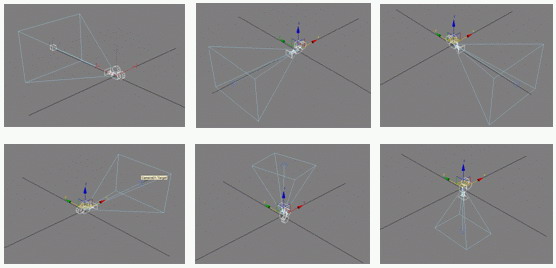
Figure 1: Light's camera in six directions for rendering the scene's depth to cubic shadow map
Thus, for the first pass we should:
- Set the camera looking the positive X axis
- set the render target to the corresponding cube face acquired in the initialization step and clear it
- Render scene depth (just like rendering depth in spot-light shadow mapping)
For the second pass:
- Set up the camera looking at the positive Y axis
- set the render target to the corresponding cube face acquired in the initialization step and clear it
- Render scene depth
And so on. Rendering the scene depth to the cubic shadow map faces is identical to normal shadow mapping, for we are using a camera and our target is a 2D floating-point texture. Here is the vertex shader that will do the job for this part:
VS_OUTPUT_DEPTH depthMap_VS( float4 inPosition : POSITION )
{
  VSS_OUTPUT_DEPTH output;
  float4 positionW = mul( inPosition, worldMat );
  output.oPositionLight = mul( inPosition, worldViewProjMat );
  output.lightVec = lightPosition - positionW.xyz;
  return output;
}
The pixel shader will just compute the length of light vector using HLSL's intrinsic function, length(), and outputs the result to flow down the pipeline. The following C++ code will do the job for the second step of implementation:
//enable red channel for color
writepd3dDevice->SetRenderState(D3DRSS_COLORWRITEENABLE , D3DCOLORWRITEENABLE_RED );
m_pShadowEffect->m_pEffect->SetTechnique(m_pShadowEffect->m_DepthMapHandle);
m_pShadowEffect->m_pEffect->Begin(&numOfPasses, NULL);

//render the scene depth to positive X side of the cube map createCamForPositiveX();
//a helper function for setting up the light's camera looking toward positive X axis
renderDepthToCubeFace(depthCubeFacePX); //render the scene depth to positive Y face of the cube map
createCamForPositiveY();
renderDepthToCubeFace(depthCubeFacePY); //render the scene depth to positive Z face of the cube map
createCamForPositiveZ();
renderDepthToCubeFace(depthCubeFacePZ); //render the scene depth to negative X face of the cube map
createCamForNegativeX();
renderDepthToCubeFace(depthCubeFaceNX); //render the scene depth to negative Y face of the cube map
createCamForNegativeY();
renderDepthToCubeFace(depthCubeFaceNY); //render the scene depth to negative Z face of the cube map
createCamForNegativeZ();
renderDepthToCubeFace(depthCubeFaceNZ);

m_pShadowEffect->m_pEffect->End(); //enable color writes
m_pd3dDevice->SetRenderState(D3DRS_COLORWRITEENABLE, D3DCOLORWRITEENABLE_ALPHA | D3DCOLORWRITEENABLE_RED | D3DCOLORWRITEENABLE_GREEN | D3DCOLORWRITEENABLE_BLUE);
Where renderDepthToCubeFace(...) and createCa() functions are:
void CCubicShadowMapping::renderDepthToCubeFace(LPDIRECT3DSURFACE9 inCubeFaceSurface)
{
  D3DXMATRIXA16 worldViewProjMat; //set and clear the cube map face surface

  if(SUCCEEDED(mpd3dDevice->SetRenderTarget( 0, inCubeFaceSurface )))
  {
    mpd3dDevice->Clear(NULL, NULL, D3DCLEAR_TARGET | D3DCLEAR_ZBUFFER, 0x00000000, 1.0f, NULL);
  }

  //render all geometries of the scene(assuming that there is no scene management or frustum culling algorithm)
}

void CCubicShadowMapping::createCamForr***()
{
  m_pLightCamera->setLook(/*m_PositiveLookX for example*/);
  m_pLightCamera->setUp(/*m_PositiveLookY for example*/);
  m_pLightCamera->setRight(/*m_NegativeLookZ for example*/);

  //update the camera's concatenated view-projection matrix with new look, up and right vectors
  m_pLightCamera->updateViewProjMat();
}
Note that since we have an R32F texture format and only the red channel is used, it's almost essential that we disable color writes except for the red channel when we render scene depth to our cube texture. Because cubic shadow maps are large textures, we need to consider fill-rate issues when using this technique.
For example, a cubic shadow with an edge size of 512 pixels, occupies (6 faces 262,144 pixels 32 bits = 6144KB) in video memory. This is why there are several optimization techniques for implementing the first part of the technique (creating the cubic shadow map). You can refer to the "Optimization" part to get familiar with these performance improvement techniques.
Step 3: Rendering the Scene using cubic shadow map
Having the cubic shadow map, it's time for implementing the final step which will do the depth comparison of each pixel with the corresponding pixel in our cube map. If the depth of the current pixel is greater than the depth sampled from the cubic shadow map, then the pixel is in shadow, otherwise it's lighted. As mentioned in the algorithm, the only difference is we sample a cube map instead of sampling a 2D texture using projective texturing.
Sampling a cube texture requires a three component vector. For this, we use the reverse of the light's direction vector which is a vector originating at the light's position pointing to the current pixel. Remember that when we where rendering the depth of each pixel to the cube map, we used the length of light vector as our depth factor. So here we will do the same thing for depth of the current pixel and sample our cube map in order to do the depth comparison. The following HLSL code is a function extracted from the effect which will compute the lighting and shadowing of the scene:
lightFuncOutput LightPointSH(float3 inObjPos, float3 inNormal, float3 inCam2Vertex)
{
  lightFuncOutput output;
  output.diffuseResult = float4(0.0f, 0.0f, 0.0f, 1.0f);
  output.specularResult = float4(0.0f, 0.0f, 0.0f, 1.0f);
  float4 PLightDirection = 0.0f;
  PLightDirection.xyz = lightPosition.xyz - inObjPos ;

  //inObjPos is the pixel's position in world space
  float distance = length(PLightDirection.xyz); //the depth of current pixel
  PLightDirection.xyz = PLightDirection.xyz / distance; //compute attenuation factor
  PLightDirection.w = max(0, 1 / (lightAttenuation.x + lightAttenuation. distance + lightAttenuation.z   distance istance) );

  //sample the cubic shadow map using the inverse of light direction
  float shadowMapDepth = texCUBE(cubeShadowMapSampler, float4(-(PLightDirection.xyz), 0.0f)).x;

  //do the depth comparison
  if(distance > shadowMapDepth)
  {
    return output; //the pixel is in shadow so only the ambient light is visible to eye
  } else { //the pixel is not in shadow so the phong lighting is applied
    float3 floatVecTmp = normalize(inCam2Vertex + PLightDirection.xyz);
    output.diffuseResult = PLightDirection.w *  lightDiffuse ax(0, dot(inNormal, PLightDirection.xyz));
    output.specularResult = PLightDirection.w * lightSpecular * pow(max (0, dot(inNormal, floatVecTmp) ), specPower);
    return output;
  }
}
And finally the vertex and pixel shader of this step is as follows:
VS_OUTPUT cubicShadowMapping_VS(float4 inPosition : POSITION, float3 inNormal : NORMAL)
{
  VS_OUTPUT output;
  float4 positionW = mul(inPosition, worldMat);
  output.cam2Vert = (eyePosition - positionW).xyz;
  output.position = mul(inPosition, worldViewProjMat);
  output.worldPos = positionW.xyz;
  output.normalW = mul(inNormal, worldMat).xyz;
  return output;
}

float4 cubicShadowMapping_PS(VS_OUTPUT In) : COLOR0
{
  lightFuncOutput lightResult;
  float3 normal = normalize(In.normalW);
  float3 cam2Vert = normalize(In.cam2Vert);
  lightResult = LightPointSH(In.worldPos, normal, cam2Vert);
  float4 ambient = materialAmbient * globalAmbient;
  float4 diffuse = materialDiffuse * lightResult.diffuseResult;
  float4 specular = materialSpecular * lightResult.specularResult;
  float4 lightingColor = (ambient + (diffuse + specular));
  return lightingColor;
}
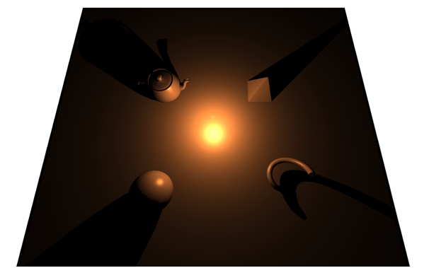
Figure 2: The final results for an omni-directional light
Optimization
The technique presented in this article is the most basic shadow mapping technique for omni-directional lights. There are several optimization and quality improvement techniques which will help the basic technique to run faster and achieve accurate results. This part will help you to get a brief understanding of these techniques but will not give details of implementation, since doing so will make this article a book on shadow mapping! With that in mind, here are some techniques you can do some research about:
The first thing that comes to mind is frustum culling. Remember that we had to render the scene six times in order to fill our depth cube map. Thus, applying frustum culling will help a lot to reduce draw calls.
The second is to reduce rendering passes of the first step as much as possible; In other words, not rendering the faces of the cubic shadow map. The depth rendering step requires six cameras, but what if the frusta of these cameras are not inside the frustum of our main camera or there are only three visible frusta, for instance. In these cases we can skip rendering, because if one of the light's frustums is not visible then the shadow it generates is not visible. This technique is easy to implement and has great impact on improving the rendering performance.
The third is to cull shadow casting objects. For this, we should create a virtual cone covering both the light and the shadow caster with its narrow side based on the light's position. Then we can perform frustum culling on this cone and decide whether the shadow caster is visible or not. If you are wondering why we use a cone instead of simply culling casters against the frustum, it's because doing so will prevent popping shadows into view.
The fourth is to define a scissor rectangle that represents the region of the screen affected by light and use the hardware's scissor test to reject any pixels that are not affected by light. This technique is also easy to implement and improves the performance vastly, for each omni-light that we place in our scene has a limited range and processing pixels beyond this range is vain.
The fifth is to use hardware shadow mapping which has been available via NVidia GeForce3 and above. Using hardware shadow mapping has several benefits such as less memory bandwidth consumption, no color buffer writes and hardware accelerated depth-only writes. Using hardware shadow mapping for normal shadow mapping is trivial but since we are using a cube texture for our depth map we cannot directly implement this technique for omni-light shadow mapping. This is because shadow depth textures (D24, D16) do not support cube textures but that doesn't mean we cannot use hardware shadow mapping with cubic shadow mapping. The solution is to merge all six faces of the cube map in a large depth texture and use special addressing techniques to sample Texels from this texture. In other words, we treat this texture as a cube map by converting our three component texture coordinate vector to a two component one for sampling this texture which is called "VSDCT" or "Virtual Shadow Depth Cube Texture".
The Source code
There are a few notes I'd like to mention about the source code of this article:
The source code is NVidia PerfHUD ready. So feel free to explore the pipeline (if you have video card that is compatible with the program) and see the visualization of the algorithm in real-time. Also you can find performance intensive parts of the algorithm and maybe come up with new ideas.
The source code is not optimized (neither the C++ nor the HLSL code) so you can add the code for optimization techniques described earlier.
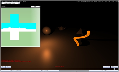
Figure 3: The sample application ran with NVidia PerfHUD
References
Gerasimov and Philipp. Omnidirectional Shadow Maps. In GPU Gems, Addison-Wesley. Pages 193-203, 2004.
G king and W Newhall. Efficient Omnidirectional Shadow Maps. In ShaderX3: Advanced Rendering with DirectX and OpenGL, Charles River Media. Pages 435-448, 2004.
About me
I am a senior student of software engineering in Azad University of Tehran(Central Branch) and have been a freelance graphics programmer for almost five years. Also, as a researcher in Shahid Rezayi Research Center(Sharif University), I have contributed in several simulation projects focusing on Graphics Programming and Rendering Techniques for two years.
Thank you for reading this article. If you have any doubts, questions or comments, please feel free to mail me at Ehsan_the_tiamat@yahoo.com.