Introduction
Current graphics hardware has built in functionality for rendering a constant number of light sources at a time. While for some scenes this constant is large enough, for many scenes it is not, and for those scenes this hardware-determined limit can be frustrating to work around. To increase the number of light sources, most developers end up having to use techniques that only approximate the lighting (like glow effects) or are slow (like looping through all the lights manually per pixel or per vertex). This article focuses on an efficient way to render hundreds of dim light sources accurately using an image space technique that takes advantage of the graphics processor's fast rasterization. This technique is very useful for scenes that have a lot of lampposts, lanterns, towns at night, lights on models, light-emitting particle effects and other scenes that have a large number of 'small' light sources. Additionally, since this technique lies in image space, the cost of the algorithm does not depend on the complexity of the geometry in the scene, only the light sources themselves. The same light sources rendered with this technique have the same additional cost whether the scene has 10K or 100K polygons.
In order to run this algorithm efficiently, the graphics card must support multiple render targets. This means that this algorithm only works for graphics cards that support DirectX 9.0 or OpenGL 2.0 (you can use extensions for MRT in earlier versions). Before reading this article, you should understand how to render to multiple targets and how to program vertex and pixel shaders.
Lighting
Before we jump into the algorithm itself, lets first briefly explain lighting, and in doing so develop intuition on how the algorithm can work efficiently. For this algorithm, we only consider lights that actually have a position and exist in world space (unlike directional lights). To render directional lights, the built-in light sources on the graphics card should suffice (as there usually are not too many directional lights). For simplicity, we will assume all light sources are point light sources, although there are simple extensions to the algorithm to render non-point light sources which I will briefly discuss later.
Let's say there are three point lights in a scene.
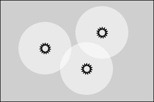
Figure 1: Three light sources in a simple scene. The black suns represent the actual light sources, and the white circles around them represent their area of effect.
These light sources cast light in all directions around them, however the power of the light source attenuates quadratically with distance. This means that the farther away from the light source a point is, the less light it receives. At some distance, the amount of light received from the light source is small enough (less than some delta) that its contribution can be considered zero. This distance defines a sphere around the light source that represents the light source's area of effect. Everything within this sphere receives light from the light source, and everything outside this sphere receives almost no light from the light source.
When rendering light sources using the hardware's built in light sources or manually looping through a list of light sources, this area of effect is ignored, and all pixels will calculate the contribution of every light source, no matter how far away it is. If the light source is large and its area of effect covers the entire screen, then no computation is wasted this way. But when rendering thousands of dim light sources (which could have an area of effect of only a few pixels), this approach ends up wasting computational power for all of the pixels where the light's contribution is negligible (outside of the light's area of effect).
If you have 1,000 point lights, each of which affects only 100 pixels on the screen (where a screen might have 1,000,000 pixels), then without considering the area of effect, you are computing lighting for 1,000 lights over 1,000,000 pixels, a total of 1,000,000,000 lighting calculations. However, if for every light source, you only compute the lighting for the pixels within that light's area of effect, then you only compute lighting for 100 pixels for each light source, for a total of 100,000 lighting calculations. This is a 10,000x speedup. Obviously, taking the light source's area of effect into account is a big win when rendering lots of small light sources - and that is the essential idea behind image space lighting, and how it can operate so efficiently.
The Area of Effect
Calculating the area of effect of a point light is a simple computation. The contribution of a light source on graphics hardware can be defined by the following: Contribution = Light Power * Cosine Term / (d ^2 * QUADRATIC_ATTENUATION + d * LINEAR_ATTENUATION + CONSTANT_ATTENUATION)
Where the light power is the power (or brightness) of the light source (a constant for each light source), The cosine term is unknown, as it depends on the normal of the point being lit, but it is strictly between zero and one, so we conservatively set it to one. The three attenuation parameters define how the light's power attenuates over distance (where d is the distance between the light source and the point). These are constants for each light source. We can then rearrange this equation to get the following:
d ^2 * QUADRATIC_ATTENUATION + d * LINEAR_ATTENUATION + CONSTANT_ATTENUATION = Light Power / Contribution
The equation is now quadratic with respect to d. To solve this equation, we set contribution variable to the smallest value we want to include in our area of effect, and solve for d. The positive solution of this equation is now the distance at which the contribution is equal to our small delta value, and beyond that distance, the contribution decreases (attenuates), so this distance defines the area of effect of the light source. We can compute this distance once for each light source (and update it if the light source changes). Using this distance, we can quickly determine if any point is within the area of effect of the light source or not (by comparing this distance with the distance from the point to the light source).
Proxy Shapes
We can now loop through all light sources per pixel, and test if that pixel is within the light's area of effect before computing the lighting. However, this will not greatly increase the speed - as branching on the GPU is slow, and a loop with an if statement for 1000 light sources for every pixel is still very expensive. Intuitively, we want to quickly figure out which pixels in image space are within our light source's area of effect, and then add the contribution of the light source only for those pixels. Luckily - there is a very fast and optimized algorithm for projecting shapes into screen space on the GPU: Rasterization. GPU rasterization can rasterize over a million triangles in real time. If we bound the light's area of effect within a low poly object - say a cube (12 triangles), we can then rasterize a cube for each light source to the screen, and the pixels in that cube represent approximately the pixels within the light source's area of effect (if it is a bounding shape, it will never under-approximate).
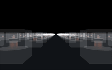
Figure 2: Bounding cubes rasterized for each point light, quickly generating pixels within the light's area of effect. Proxy cubes shown as transparent boxes, transparent circles depict the actual area of effect projected on the ground.
If the GPU can render a million triangles and each light source's proxy shape is a cube (12 triangles), then we can potentially render over 80,000 light sources! Practically, we cannot achieve anywhere near 80,000 light sources, but this shows how using rasterization can easily and efficiently generate the pixels within each light source's area of effect.
Rendering and Implementation
Now that we know the theory behind image space lighting, it is time to work out the actual rendering and implementation details. The steps to rendering image space lighting are as follows:
- Extract the position, normal and color information of the scene to calculate the lighting at any pixel. This can be done with deferred shading, where the scene is rendered once with a pixel shader that stores the position, normal and color information into the proper render targets. Any effects like normal mapping can be done here - just outputting the final normal to the normal texture.
- Render the scene to the screen normally (as it was rendered off screen previously). However, this does not require rendering the scene geometry again, as the per pixel attribute results were already generated in the deferred shading pass. Simply render a quad that fills the entire screen (this is easy to do with a vertex shader), and then retrieve the per pixel position, normal and color information from the deferred shading textures. During this pass, any primary light sources (like directional lights) and effects can be rendered (the contribution to the scene from the point lights will be added later). It is worth noting that the pixel shader only executes once per pixel in this pass, which can improve the speed of the rendering for complex pixel shaders.
- Render the point lights on top of the previously rendered scene as follows:
-
- Bind a shader that computes the lighting contribution from the light source whose proxy shape is being rendered on the point at the rasterized pixel position in the deferred shading textures. This shader can also discard the fragment if the point is not within the light's area of effect to save computation costs (which happens because the proxy shape over-bounds the area of effect and because the depth test is disabled when rendering the proxy shapes (see below), so the point could be far away in the depth coordinate).
- Set the blending function to 1 * src + 1 * dst. This indicates that the computed lighting at each pixel is added to the previous value. As the lighting equation is additive (summation of the contribution of all light sources), this works as expected.
- Enable face culling, and cull front faces. If the back faces are culled, nothing will be rendered when the camera moves inside the proxy shape (as the front faces will be behind the camera). As long as the proxy shape is convex, there are only two rasterized fragments for each pixel on the shape (one on the front face, and one on the back face). If the front faces are culled, only one fragment is rasterized per pixel, which means that no light will contribute lighting twice for any pixel (which would be incorrect).
- Disable the depth test as pixels on the back face of the proxy shape could fail the depth test (thus contributing no light) even when the light source should contribute light to that pixel. However, since the pixel shader can quickly discard pixels outside of the light source's area of effect, this does not affect performance too much.
- Render all of the proxy shapes. The proxy shapes can be stored in a tree structure to quickly render only the proxy shapes within the view frustum to improve performance.
- Finally, unbind the shader and textures, and then set blending, face culling and depth test back to their previous values.
Code Snippets
Below is an OpenGL code snippet from the game project Aero Empire [2], which renders the point lights following the above implementation. Shader* cur_shader; void renderLight(Light* light){ //pass light world position to pixel shader cur_shader->setUniformVec3("lightWorldPos", light->getWorldPosition()); //pass light color (magnitude of vector is power) to pixel shader cur_shader->setUniformVec3("lightColor", light->getColor()); //pass the light's area of effect radius to pixel shader cur_shader->setUniformFloat("lightAoE", light->getAoERadius()); light->render(); //render the proxy shape } void renderLights(const Shape* scene){ //set blend function glBlendFunc(GL_ONE, GL_ONE); //cull front faces glEnable(GL_CULL_FACE); glCullFace(GL_FRONT); //disable depth testing glDisable(GL_DEPTH_TEST); glDepthMask(false); //bind point light pixel shader Shader* shader = shaders[SHADER_LIGHT]; shader->bind(); //bind position, normal and color textures from deferred shading pass bindTexture(positionMap, POSITION_UNIT); shader->setUniformInt("positionMap", POSITION_UNIT); bindTexture(normalMap, NORMAL_UNIT); shader->setUniformInt("normalMap", NORMAL_UNIT); bindTexture(colorMap, COLOR_UNIT); shader->setUniformInt("colorMap", COLOR_UNIT); bindTexture(attrMap, ATTR_UNIT); shader->setUniformInt("attrMap", ATTR_UNIT); //set pixel shader attribute "camPosition" to the camera pos //(as it is needed for Phong shading) camera.loadCameraPosition(shader, "camPosition"); shader->setUniformFloat("d_sx", 1.0/width); shader->setUniformFloat("d_sy", 1.0/height); cur_shader = shader; //run renderLight function on all light proxy shapes in scene getLights(scene, &renderLight); //unbind and reset everything to desired values shader->unbind(); unbindTexture(POSITION_UNIT); unbindTexture(NORMAL_UNIT); unbindTexture(COLOR_UNIT); unbindTexture(ATTR_UNIT); glDisable(GL_CULL_FACE); glEnable(GL_DEPTH_TEST); glDepthMask(true); } Below is the GLSL pixel shader bound above which computes the lighting (the vertex shader only sets gl_Position = ftransform() ). //input parameters uniform sampler2D positionMap, normalMap, colorMap, attrMap; uniform vec3 camPosition, lightWorldPos, lightColor; uniform float lightAoE, d_sx, d_sy; void main(void) { //calculate screen coord vec2 coord = vec2(gl_FragCoord.x*d_sx, gl_FragCoord.y*d_sy); //get the position from deferred shading vec4 position = texture2D(positionMap, coord); //vector between light and point vec3 VP = lightWorldPos-position.xyz; //get the distance between the light and point float distance = length(VP); //if outside of area of effect, discard pixel if(distance > lightAoE) discard; //normalize vector between light and point (divide by distance) VP /= distance; //get the normal from deferred shading vec4 normal = texture2D(normalMap, coord); //get the color from deferred shading vec4 color = texture2D(colorMap, coord); //get lighting attributes from deferred shading vec4 attributes = texture2D(attrMap, coord); float diff_coefficient = attributes.r; float phong_coefficient = attributes.g; float two_sided = attributes.b; float cos_theda = dot(normal.xyz, VP); //calculate two sided lighting. cos_theda = (cos_theda < 0.0)?-two_sided*cos_theda:cos_theda; //calculate diffuse shading float diffuse = diff_coefficient*cos_theda; //calculate half vector vec3 H = normalize(VP+normalize(camPosition - position.xyz)); //calculate Phong shading float phong = phong_coefficient*pow(max(dot(H, normal.xyz), 0.0), 100.0); //calculate light contribution with attenuation vec3 C = lightColor*(color.rgb*diffuse+phong)/(distance*distance+0.8); //all lights have constant quadratic attenuation of 1.0, with a constant attenuation of 0.8 to avoid dividing by small numbers gl_FragColor = vec4(C, 1.0); //output color } If you are planning to add lanterns or lamps, adding two-sided lighting allows for point lights inside a lampshade or lantern to contribute light to it. The above shader includes a very simple implementation of two-sided lighting.
Results
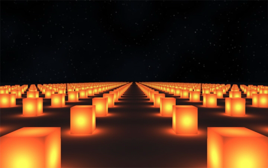
Figure 3: 2175 bright cube lanterns rendered on a flat plane in a night scene.
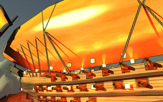
Figure 4: A daytime rendering of a blimp from Aero Empire [2] with lanterns during the day. Notice the Phong lighting on the envelope.
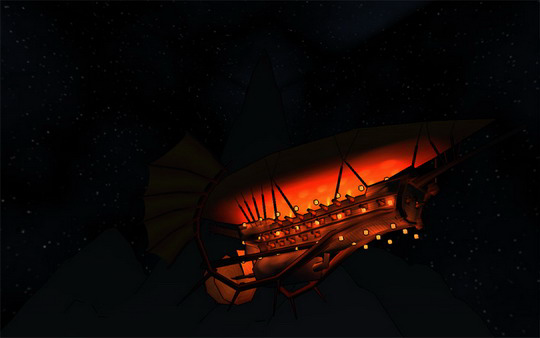
Figure 5: A nighttime rendering of the same blimp as above.
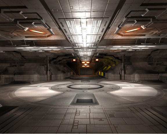
Figure 6: Ship hanger interior from Infinity [3]. This rendering includes both point lights and ambient lights (adding point lights that approximate indirect lighting).
As you can see, image space lighting creates accurate lighting effects that add to the scene whether daytime or nighttime, interior or exterior. The ability to efficiently render a large number of point light sources allows for much more diverse lighting environments which greatly improves the rendering of the scene, yet still runs in real time.
Performance
The cost of this algorithm depends solely on the number of point lights rendered and the number of pixels within each light's area of effect. The number of lights determines the overhead of the rasterization step. Without this overhead, in the worst case where the area of effect of all lights is the entire screen, the algorithm would simply add the contribution of every light for every pixel (which would have the same cost as rendering all of those lights by looping over all lights per pixel). However, there is also the overhead of the rasterization step, which is small (as modern rasterizers can handle a million triangles), but is worth noting. The number of pixels rasterized from the proxy shapes determines the main performance hit for this algorithm. Point lights that are very bright, or are very close to the camera end up generating a large number of pixels. While one or two point lights filling the entire screen does not impact performance too much, having many of such point lights is the main bottleneck of image space lighting. This algorithm performs better when the point lights are not clustered, for if the camera is close enough to one point light for it to fill the screen, then the other point lights are farther away and so have a smaller area of effect in screen space (as long as the points are not clustered).
To increase performance out of this algorithm - reduce point light usage, decrease point light brightness, and spread point lights out more (you can always approximate a cluster of point lights with a single brighter point light).
Below are some performance results of this algorithm. All results are from rendering a lantern scene (like Figure 3) at a resolution of 600x400 on a GeForce 9200M GS. The ground is a 2000x2000 unit plane, and lanterns (12 triangles with a point light inside) are scattered in 50x50 unit clusters that are uniformly distributed on the ground plane. The camera is guaranteed to be close to one of those clusters (worst case). The light shader computes two-sided lighting for diffuse surfaces, and the deferred shading pass renders to four 32-bit floating-point textures.
Clusters is the number of clusters generated, lights is the number of lights per cluster generated, ISL # is the fps of the image space lighting algorithm where all lights have an area of effect radius # units (where the area of effect is determined by the brightness of the light and the cutoff threshold), and PPS is the fps of a naive direct loop of all lights per pixel (per pixel sum).
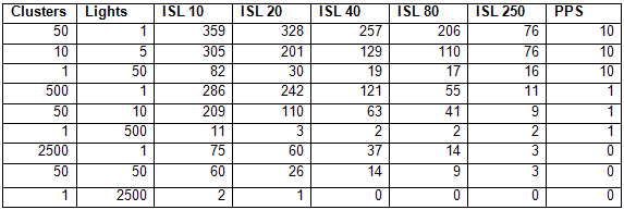
This shows that if the lights are not very clustered or bright, the image space lighting technique can render hundreds of point lights without too much of a performance hit. In the worst case, where the camera is near a single cluster with many point lights, the image space lighting technique still outperforms the per pixel sum algorithm when the lights are dim, however as the lights get brighter, the image space lighting algorithm slowly converges towards the speed of the per pixel sum algorithm (as it has to compute the lighting for each light source for each pixel).
Downsides and Possible Solutions
There are three major downsides to Deferred Rendering (the first step to Image Space Lighting). All of these downsides come from the fact that you have to store all necessary geometric attributes into textures. The first downside is just the sheer amount of memory storage required (which can be quite limited, depending on the graphics card). In the demo code, I store the position, normal, diffuse color, diffuse component, specular component, and two-sided lighting component. This ends up being 9 32 bit floating point values, 1 32 bit depth value, and 4 8 bit unsigned byte values, for a total of 44 bytes per pixel. For a standard screen size of 1024x768, that is 786,432 pixels and a total of 33 megabytes. When a graphics card only has 128 megabytes dedicated memory, that's about a fourth of the memory space used, which can be a problem when you also need to store vertex buffer objects (triangle mesh data stored on the GPU) and textures for the various objects in the scene. The storage of geometric data into textures is called a G-Buffer (standing for geometric buffer), and there are several tricks to bring its size down, like using 16 bit floating point values, spherical coordinates, storing the position as just a depth value, etc. In general, you want to compress and pack the data in a way that saves a lot of memory, however, this can also cause banding and other artifacts if you aren't careful.
The second downside is anti-aliasing. Since you only store the geometric attributes per pixel, you lose the hardware anti-aliasing that allows you to blend edges by computing sub pixels. This causes aliased jagged edges that you have probably seen if you have rendered a scene without anti-aliasing. There are several ways to add anti-aliasing to a deferred rendering approach, like rendering to a larger buffer and then downsampling (however, this requires even more memory and the computational cost of averaging), and doing edge detection and blurring around the edges (which adds computational cost and does not take into account the sub pixels, so it's not a very effective form of anti-aliasing). The ideal solution would be to generate and store sub pixels only where needed (like at the edges, which wouldn't increase the memory cost too much), but this would require hardware support and extensions, as graphics card typically only render to a framebuffer (2D texture or buffer).
The final downside is alpha blending. Related to anti-aliasing, sometimes you need to generate multiple samples for certain pixels, but by rendering to a texture, you lose this information (as you can only have one sample per pixel). With alpha blending, you want a semi-transparent object to blend on top of the object behind it, however, this requires the geometric data of the foreground and background object to be stored in the same pixel. Again, with hardware support and extensions for rendering to structures other than framebuffers, you could store all of these samples and easily render scenes with alpha blending. However, without this hardware support, the best way to add alpha blending to deferred rendering scenes is to render the opaque surfaces first, and then render the alpha-blended surfaces on top (however, if they are rendered on top, then they do not get any light contribution from the point lights).
Other Light Types and Effects
Adding spotlights and non-point lights simply requires calculating that light source's area of effect, and computing a bounding proxy shape for it. For non-point lights, this is a little more complex, as the area of effect may not be spherical. Additionally, the pixel shader would have to handle rendering the different lighting types. Other than that, the algorithm should work the same - for each pixel, add the contribution of all light sources where the point lies within the light source's area of effect. I have not experimented with non-point lights, but if anyone tries, feel free to share the results. Adding area light sources is also possible by approximating the light with many small point lights (a common approximation for rendering area lights). This allows for light sources that have different shapes (long, square, etc).
Additionally, instead of rendering light sources, you can use this technique to render light patches (for indirect illumination). The C. Dachsbacher and M. Stamminger's paper, "Splatting Indirect Illumination" [1] uses rasterization to compute surface patches that receive direct lighting, and then computes the lighting received from those patches for all pixels within that patch's area of effect (as done in image space lighting). This quickly renders an approximation to one bounce indirect illumination.
Currently, there are difficulties in casting shadows from these light sources efficiently. Sampling occlusion from a large number of light sources is a tough and expensive problem - and is usually solved by generating shadow maps for clusters of lights. However, since the lights rendered by this algorithm are dim, the fact that they do not cast shadows is not incredibly noticeable.
Conclusion
Any game that wants to simulate complex lighting effects from a large number of light sources could benefit from this technique. Very few games use more than the hardware's built-in light sources, and most of the smaller light sources are approximated with glow or light maps. This technique is offered as an alternative to glow and light maps that is still efficient, yet computes accurate lighting effects. This technique would be especially impressive for games with night scenes that are lit up by many small point lights. As a real world example of image space lighting, it is implemented in the game Aero Empire (which I am currently developing). The reason for adding it is mainly for rendering lanterns, which will be common within towns and on the blimps. They will allow for operation of blimps at night, towns lit up by lanterns at night, and lights for the interiors of blimps and buildings (which would be dark otherwise due to shadows). This is one example of how image space lighting can be used in a game. It is my hope that other games will use this technique to add more complex and interesting lighting environments to their graphics programs as well.
Infinity: The Quest for Earth is another real world example of a game that has included image space lighting. F. Brebion, developer of Infinity, implemented a technique similar to image space lighting to improve the interior of hangers and hulls of the ship - which would otherwise be dark when only including light from the sun. The inclusion of indirect lighting also greatly improved the realism of the rendered scenes. See Brebion's journal on deferred lighting for more information on this [3]. Infinity is another great example of how image space lighting can be used to efficiently add more complex lighting environments.
If you have any questions, improvements or results from using this algorithm that you would like to share, feel free to post in the comments or contact me at [email="terra0nova@hotmail.com."]terra0nova@hotmail.com[/email].
Further Reading / Sources
I have included the source code for rendering a lantern scene at night with the image space lighting technique. Feel free to fiddle with the code and put together more complex scenes as well. This code should be considered free to use and modify, so long as you give proper credit where due. [1] C. Dachsbacher , M. Stamminger. Splatting Indirect Illumination. 2006.
[2] Collaborative Game Project. Aero Empire. 2009.
[3] F. Brebion. Deferred Lighting and Instant Radiosity. 2009.

