Fixed and scaled CHIP-8/SCHIP interpreter

Published September 24, 2008
Advertisement
The CHIP-8/SCHIP interpreter now seems happy enough to run games, though the lack of settings to control how fast or slow they run makes things rather interesting.


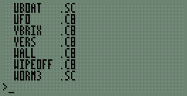
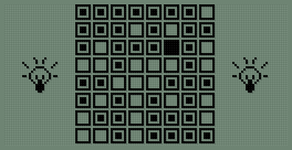
First of all, I've hacked together a painfully simple read-only file system. Each file is prefixed with a 13-byte header; 8 bytes for the filename (padded with spaces), 3 bytes for the extension (padded with spaces) and two bytes for the file size. The above file listing can be generated by typing *. at the BASIC prompt.

I've written a new sprite drawing routine that scales sprites up to double size when in CHIP-8 mode; this allows CHIP-8 games to fill the entire screen. Unlike the existing sprite code, which I've retained for SCHIP games, it runs entirely from ROM; the existing sprite code has to be copied to RAM as it uses some horrible self-modifying code tricks. I should probably rewrite that bit next. [smile]

As for the bug I mentioned in the last post, it was because of this:
; --- snip ---; Group 9:;   * 9XY0 - Skips the next instruction if VX doesn't equal VY.InstructionGroup.9	call GetRegisterX	ld b,a	call GetRegisterY	cp b	jp nz,SkipNextInstruction; Group A:;   * ANNN - Sets I to the address NNN.InstructionGroup.A	call GetLiteralNNN	ld (DataPointer),hl	jp ExecutedInstruction; --- snip ---

If an instruction in the form 9XY0 is executed and VX == VY, rather than jumping to ExecutedInstruction the code runs on and executes the instruction as if it had been an ANNN as well, which ended up destroying the data pointer. Adding a jp ExecutedInstruction after the jp nz,SkipNextInstruction fixed the bug.

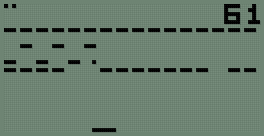
One other advantage of the zoomed sprites is that "half-pixel" scrolls also work correctly:


...not that I've seen any game that uses them.


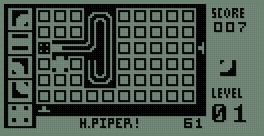
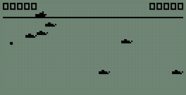
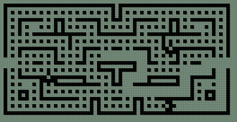
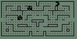
The last two screenshots show two versions of the game Blinky, one as a regular CHIP-8 program and the other taking advantages of the SCHIP extensions.
0 likes 3 comments

Comments

nerd_boy
Lovely work, benryves.

In regards to some of the things you mentioned in this and the previous post, a few random things that popped into my head that may or maynot help:

The problem of 2MHz to 10Mhz, do you have enough memory anywhere to have an screen buffer that you could just blit to the screen when the timing is appropriate? That way you could run at 10Mhz for the code and draw whenever. Of course, that would require that all S/CHIP-8 progs wait on one of the timers, not sure if they do or not. :/ <edit>So, wait. In your previous post, it stated that you already had a buffer since you had to rotate bits of it before sending it to hardware. So would this even be feasible?</edit>

As for the timer, anyway you could check the clock(I think you said it was $D0) and rig up something like:

omgagotolabel:
foo=GetClock();
// Perform single operation?
while(GetClock()<foo+SOME_TIME);
soundTimer-=(GetClock()-foo)/whatever;
otherTimer-=(GetClock()-foo)/whatever;
goto omgagotolabel;

Kinda ugly, I know. You could just combine it with the idea above, and do all of the instructions until it is time to draw. That would also provide a way to make the gameplay faster or slower.

Again, may not be feasible given your hardware setup. But meh. [disturbed]
September 27, 2008 02:20 PM
benryves
Thanks for the comments. [smile]
Quote:Original post by nerd_boy
The problem of 2MHz to 10Mhz, do you have enough memory anywhere to have an screen buffer that you could just blit to the screen when the timing is appropriate? That way you could run at 10Mhz for the code and draw whenever. Of course, that would require that all S/CHIP-8 progs wait on one of the timers, not sure if they do or not. :/ <edit>So, wait. In your previous post, it stated that you already had a buffer since you had to rotate bits of it before sending it to hardware. So would this even be feasible?</edit>
This is very much a hardware problem. Each component has various timing restrictions, and for the most part the components I have respond quickly enough to be usable at 10MHz. The LCD is the exception here. To write data to or read data from it you need to set its control pins to the correct state, then hold its enable pin low for at least 450nS, then hold its enable pin high for at least 450nS. The inner part of the Z80's read or write cycle is about 2.5 clock cycles. At 10MHz, a clock cycle is 100nS; 250nS is not enough for the 900nS LCD access cycle. Dropping the CPU to 2MHz gives ample time to access the LCD (1250nS).

I had planned on having a way to switch between 2MHz and 10MHz modes in software. However, the "multiplexer" I designed (which can be used to switch between either the native 10MHz clock or the 2MHz clock derived by dividing this by 5) takes time to settle in its new state. During this transition period the signal can oscillate high and low very rapidly, generating spurious clock signals far in excess of 10MHz. The Z80 and the rest of the system can't respond quickly enough, invalid data ends up on the data bus and it crashes.

One possible fix I've just thought of would be to have a 20MHz clock, divide this by two to get a 10MHz "fast" clock and that by 5 to get a 2MHz "slow" clock. I'd use the multiplexer as above, but feed its output via a latch with the latch's clock input connected to the master 20MHz clock. This latch would only let a new signal (high or low) through at a rate of 20MHz, which would limit the maximum clock speed to 10MHz.

The "correct" solution is to use the Z80's /WAIT pin. By holding this low, the Z80 can be paused during I/O or memory operations to allow for slow hardware. However, building the state machine/timer to handle this as well as the Z80-unfriendly hold-low-then-hold-high LCD enable pin would be much more complex.

Quote:As for the timer, anyway you could check the clock(I think you said it was $D0) and rig up something like:
The clock chip only has a resolution of 1 second. However, it can generate square waves at the following frequencies: 1Hz, 4096Hz, 8192Hz and 32768Hz. Dividing a 4096Hz signal by 40 gives a 102.4Hz signal that could be fed into the Z80's interrupt mechanism (via the /INT pin). This would mean that 102.4 times a second, the Z80 would call address $38, where a service routine would update the timers. I use this method on the TI-83+ version, where it works well.
September 27, 2008 08:49 PM
nerd_boy
Ah.
September 28, 2008 02:28 AM
You must log in to join the conversation.
Don't have a GameDev.net account? Sign up!
Advertisement