On the one hand this design has a certain purity, but it ties the CPU up every time data is to be transferred. The keyboard sends data when it feels like it, so if you wished to perform some function based on a key press event you'd need to poll the port periodically, assuming that if communications time out there's no key waiting. All this hanging around does nothing good for performance.
As it turns out I found a PIC16F84 in an old school project over the weekend, so downloaded its datasheet and the MPLAB IDE and tried to puzzle it out.
The 16F84 is a pretty venerable microcontroller with a 1K flash memory for program code, 68 bytes of data RAM and 64 bytes of data EEPROM. It can run at up to 10MHz, and is based on a high-performance RISC CPU design. It has 13 digital I/O pins, each of which can be configured individually as either an input or an output. I'm well aware there are far better microcontrollers around these days, but this one was just sitting around doing nothing.
;if(img.style.backgroundImage){img.style.backgroundImage='url('+img.src+')';img.src=imgs[img.src==imgs[1]?2:1]}else{img.style.backgroundImage='url('+img.src+')';img.src=imgs[2];};void(0);)
Click to toggle labels
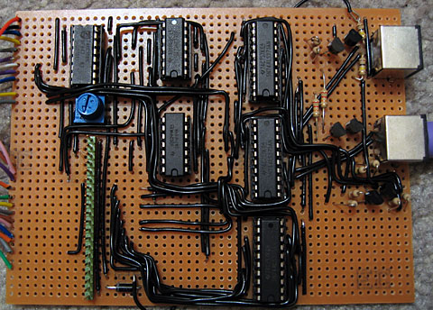
Above is the circuit I constructed to work with the 16F84. The HRM538BB5100 in the top-right is an infrared demodulator and amplifier module; it will output 5V until it receives a 38kHz infrared signal (such as the one emitted by most remote controls) at which point it outputs 0V. By timing the lengths of the IR pulses one could decode a remote control signal, and that's the aim of this project - decode a command from a Sony remote control and display it on the two 7-segment displays. The 10MHz crystal is probably overkill for this simple task, but it's the slowest I had available!
In fact, the 10MHz crystal works out quite neatly. Most instructions execute in one instruction cycle, which is four clock cycles. Four clock cycles at 10MHz is 400nS. The 16F84 has an internal timer that counts up after every instruction cycle and triggers an interrupt when it overflows from 255 back to 0; 400nS*256=102.4us. If we call that 100us (close enough for jazz) then it overflows 10 times every millisecond. The SIRCS protocol is based around multiples of 0.6ms, which makes this rate very easy to work with.
; ========================================================================== ;; Pins: ;; RB0~RB6: Connected to A~G on the two seven-segment displays. ;; RB7: Connected via a 220R resistor to cathode of the left display. ;; Inverted and connected via a 220R resistor to right display's ;; cathode. ;; RA0: Connected to the output of the HRM538BB5100. ;; ========================================================================== ;#include <p16F84.inc> list p=16F84 __CONFIG _CP_OFF & _WDT_OFF & _PWRTE_ON & _HS_OSC; ========================================================================== ;; Variables ;; ========================================================================== ; udataIsrW res 1 ; Temporary storage used to preserve state during theIsrStatus res 1 ; interrupt service routine.Display res 1 ; Value shown on 7-segment displays.PulseTimer res 1 ; Counter to time the length of pulses.BitCounter res 1 ; Number of bits being received.Command res 1 ; SIRCS command.; ========================================================================== ;; Reset ;; ========================================================================== ;ResetVector code 0x0000 goto Main; ========================================================================== ;; Interrupt Service Routine ;; ========================================================================== ;ISR code 0x0004 ; Preserve W and STATUS. movwf IsrW swapf STATUS,w movwf IsrStatus ; Update value shown on two 7-segment displays. movfw Display btfsc PORTB,7 swapf Display,w andlw h'F' call Get7SegBits btfss PORTB,7 xorlw b'10000000' movwf PORTB ; Increment pulse timer. incfsz PulseTimer,w movwf PulseTimer ; Acknowledge timer interrupt. bcf INTCON,T0IF ; Restore W and STATUS. swapf IsrStatus,w movwf STATUS swapf IsrW,f swapf IsrW,w retfie; ========================================================================== ;; Times the length of a "low" pulse. ;; ========================================================================== ;; Out: W - Length of pulse. ;; ========================================================================== ;TimeLow clrf PulseTimerTimeLow.Wait btfsc PORTA,0 goto TimeLow.GoneHigh incfsz PulseTimer,w goto TimeLow.WaitTimeLow.GoneHigh movfw PulseTimer return; ========================================================================== ;; Times the length of a "high" pulse. ;; ========================================================================== ;; Out: W - Length of pulse. ;; ========================================================================== ;TimeHigh clrf PulseTimerTimeHigh.Wait btfss PORTA,0 goto TimeHigh.GoneLow incfsz PulseTimer,w goto TimeHigh.WaitTimeHigh.GoneLow movfw PulseTimer return; ========================================================================== ;; Convert a hex nybble (0-F) into a format that can be displayed on a 7-seg ;; display. ;; ========================================================================== ;; In: W. Out: W. ;; ========================================================================== ;Get7SegBits addwf PCL, f dt b'00111111' ; 0 dt b'00000110' ; 1 dt b'01011011' ; 2 dt b'01001111' ; 3 dt b'01100110' ; 4 dt b'01101101' ; 5 dt b'01111101' ; 6 dt b'00000111' ; 7 dt b'01111111' ; 8 dt b'01101111' ; 9 dt b'01110111' ; A dt b'01111100' ; b dt b'00111001' ; C dt b'01011110' ; d dt b'01111001' ; E dt b'01110001' ; F; ========================================================================== ;; Start of the main program. ;; ========================================================================== ;Main ; Set PORTB to be an output. bsf STATUS,RP0 clrw movwf TRISB bcf STATUS,RP0 ; Configure TMR0. bsf STATUS,RP0 bcf OPTION_REG,T0CS ; Use internal instruction counter. bcf STATUS,RP0 ; Enable TMR0 interrupt. bsf INTCON,T0IE bsf INTCON,GIE clrf Display; ========================================================================== ;; Main program loop. ;; ========================================================================== ;LoopWaitCommand ; Loop around waiting for a low to indicate incoming data. btfsc PORTA,0 goto WaitCommand ; Start bit (2.4mS). call TimeLow ; Check that it's > 2mS long. sublw d'20' btfsc STATUS,C goto WaitCommand ; w<=20 ; Reset the command variable and get ready to read 7 bits. clrf Command movlw d'7' movwf BitCounter ReceiveBit ; Time the pause; should be < 1mS. call TimeHigh sublw d'10' btfss STATUS,C goto WaitCommand ; Time the input bit (0.6ms = low, 1.2ms = high). call TimeLow sublw d'9' ; Shift into the command bit. rrf Command,f decfsz BitCounter,f goto ReceiveBit bsf STATUS,C rrf Command,f comf Command,f movfw Command movwf Display goto Loop; ========================================================================== ;; Fin. ;; ========================================================================== ; endThe final source code is above. I'm not sure how well-written it is, but it works; pointing a Sony remote control at the receiver and pressing a button changes the value shown on the seven-segment display. PICmicro assembly is going to get take a little getting used to; instructions are ordered "backwards" to the Intel order I'm used to (op source,destination instead of the more familiar op destination,source) and as far as I can tell literals default to being interpreted as hexadecimal as opposed to decimal.
With some luck I can now teach the 16F84 the AT protocol and replace a large number of parts on the Z80 computer project with a single IC. It does feel a little like cheating, though!


I am posting this comment because you have said recently that although you are using an AT keyboard you would like to get it working properly with your Z80 computer.
I also had one working (more or less) for a while with a PIC chip on my Z80 Interak computer - but I have recently been through the code carefully and made it as simple and efficient as possible. It now works very well and is reliable.
This is the link to the code and hex files
www.interak.pwp.blueyonder.co.uk/PCtoASCII.htm
I hope you will find it useful, Alan
(or type 'interak' into google and it is usually the top site)